Use the Arduino as a low cost/power/size Monitor to keep an eye on the power consumption, temperature and door locking status of the flat. Once the data is collected it needs to be shoved somewhere it can be store, processed and displayed.What Equipment did you use?
- 1 Arduino
- 1 Adafruit Ethernet shield
- 4 DS18S20 1-wire temperature sensors
- 1 Phototransistor with inbuilt opamp
- 1 Remote server
Block Diagram
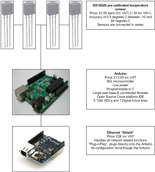
I used the Xport Ethernet shield because the official shield hadn’t been created yet. You should use the Official shield, its much easier.
Why choose expensive 1-wire sensors?
The first reason is accuracy, second pre-calibration and lastly it gives out checksumed digital readings. Another useful bonus is the unique addresses assigned by the manufacturer. This allows you to “daisy chain” devices on the same bus, freeing valuable IO lines.
The Build: Arduino – 1-wire interface
I started with the temperature sensors. I’d never used the 1-wire protocol before, and was keen to see if it was worth the fuss. There are two ways to connect these badboys: Parasitic power mode, and normal power mode, quoting from the Arduino Playground: When operating in parasite power mode, only two wires are required: one data wire, and ground. At the master, a 4.7k pull-up resistor must be connected to the 1-wire bus. When the line is in a “high” state, the device pulls current to charge an internal capacitor.
This normally takes about 3/4 of a second, meaning it would take three seconds to get four readings. I found that it wasn’t that reliable and spewed out lots of default readings of 85 Degrees Celsius. Going for the normal power mode seemed like the most sensible thing.In the finished sketch I borrowed borrowed heavily from the playground example, only taking out a few checks, making the variable more friendly, and adding a Float to string converter (the Arduino is now capable of printing Floats natively, so you wont need that any more.)

Here is the sensor mounted on a tiny piece of strip board three holes wide, and four holes long. It turns out soldering this together without the use of a third hand is decidedly difficult. The helping hands crocodile clip contraptions that pop-up every now and then are well worth the money/time spent to procure one.
Cling film is used to provide some sort of waterproofing. You can clearly see the three strands of singl e core wire tied together with a smaller piece wire. Unless you’re fond of bulky, messy, easily tangle-able, and unexpected sharp pointy bits, I would recommend the use of some thin multi-core cable. (When I move to the new flat I shall most likely use Cat5/6)
Compared to the temperature sensor, the power sensor it trivially simple to work with. In the flat I am gifted with a digital power meter, which flashes every 1/1000th of a kilowatt hour. All I had to do was glue/tape/affix a phototransistor to the LED on the meter. Then its just a case of watching the voltage change on one of the Analogue pins.I chose a Phototransistor with an inbuilt opamp. I could have used a Light Dependent Resistor, however they are slow and generally nasty. The inbuilt Opamp outputs a nice easy voltage range (0v to just under VCC), as opposed to very small current has to be amplified, and converted into a voltage range.
I used the wonderful Ethernet sheild from Lady Ada. She writes a brilliant tutorial, much better than anything I could write. However recently the arduino conglomerate have come up with the “official” Ethernet Shield. The library that comes with the official shield takes much of the pain out of internetsThe Build: Arduino Housing
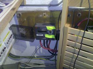
As you’ll see, I spent lots of time and money making the enclosure look like an Vegan ice creme tub. To provide a bit of portability/flexibility I’ve screwed audiojacks into the side of the tub. They have the advantage that they are both cheap and common. The temperature jacks are wired in parallel.


The yellow tape tells me which sensor is which. Highly recommended. The white cable is the network cable.
As you may have noticed, there is a distinct lack of door lock sensors. I installed this system in rented housing, which precludes me from fiddling majorly with locks. I’m sure with some silver foil and glue I could have knocked up a working sensor, but I simply never got round to it.

