New house, new monitoring system
After moving to the secret batcave, I needed to update the
monitoring system. The new house has solid concrete floors, walls and
ceilings. This means no long cables, unless I want to embed cable
runs in the walls.
Fortunately there is an easy answer, The JeeNode.
Its effectively a tiny arduino with a wireless transceiver tacked on
the top. The IO pins are arranged into 4 “ports” making
interfacing hardware on veriboard a little easier.
Low Powered Server
In the previous system I used an arduino with an ethernet shield
to collect all the sensor information and pass it to the webserver.
However I didn’t really code it very well, and it was impossible to
maintain without a complete rewrite. It also took far to long to
transmit a power/temperature reading.
I was given a sheevaplug for a birthday present. It’s
a low powered arm linux box, that fits inside a wall wort. It takes
about 7 watts to run, which is about the same as the power adaptor
that used to run the previous system. It has a USB port that kicks
out 500ma more than enough to power a few JeeNodes. I decided to use
the sheevaplug to do a bit more processing “In House” as it were.
See you later Data Aggregator
The previous data logger and grapher were written in a mixture of
Perl and PHP. The data logger wasn’t very reliable, it used to crash
every three or four weeks. Sadly it used to crash with out a trace,
so I never really got to the bottom of the problem. A cron job would
check if the data logger was running, and relaunch it if need be.
This was obviously all bollocks and needed ripping out and starting
again.
The graphing worked pretty well, and as it was custom made I could
generate massive graphs at insane resolutions. However Cacti is much
easier and more expandable, has a wide range of options, and more
importantly is widely used. This means if I search for “how to do X
with cacti” Proffessor Google usually has an answer.
Argghhh [Expletive removed] Exceptions
At work I was surrounded by Python fanatics. In the world of Post
Production python has really started to take off. Most of a films
pipeline is gaffered together with poorly written python. By osmosis
I’d learnt more and more python, so I decided to rewrite the data
logger in python.
Python is has a wonderful implementation of object orienting, its
very clean and simple. Sadly the way it handles strings is a little
backwards, but nothing disastrous. Exceptions however, are a massive
pain. I see the why they are a good idea, they even make debugging
easier. However _Everything_ throws an exception. Its sort of like
going back to GOTO in BASIC, but with the added bonus of not knowing
when your code will cockup. So you’ve got two choices, wrap
everything in try except clauses to gaurentee every function is
atomic, or just wrap the entire programme in an exception catcher,
nasty clunky and not very useful.
Exceptions are great for when things goes horribly wrong, like
writing to a file thats not open. However I don’t want my entire
programme to fall apart because I’m concatenating a int to a string.
One could use printf, however its not 1979.
Rough Diagram

Protocol Design
The RF12 library handles the transmitting and
reciving of the data. All you need to do is give it a data structure
to send and receive. The RF12 has the facility to set both address,
and address groups(similar to subnets). Those are great, but can be
tricky to set and debug. To get round this all of my node have the
same physical address. This means I can control the addressing.
Each packet contains an 8 bit packet type, which isn’t really used
that much. I’ve put in 8 bits for addressing, 4bits for the “to”
and 4bits for the “from” field. The sensor “fields” are
simple floats, there isn’t really much need for the precision, a
better C programmer would have used fixed point and saved a lot of
space. With a bit more packing the battery & power blip flag
could be jammed together as well.
Here is the struct that I’m using:
struct Packet {
//must add up to less than 65
bytes//packet counter, will roll
over, incrementsunsigned int count;
//add your sexy flags here
char packType;
//two nibbles of address
//to – from
//below is a broadcast packet
from node 8//B00001000
char address;
//no more than 61 bytes.
//anything after this is
optional, so add and remove as you see fit//char message[60];
float sensor1;
float sensor2;
float sensor3;
float sensor4;
char power;
char battery;
};
Node design
There are three node types: Receiver, Low powered temperature
monitor and Power monitor. The receiver is the node that is connected
to the server, it merely acts as a bridge to the sensor network.
There isn’t any need for special power saving tricks, as its plugged
straight into a rich source of power.
The Low Powered Temperature Monitor is designed to run off
batteries. It therefore needs to be as low power as possibly.
Fortunately Jeelabs has provided an excellent wrapper for the AVR
sleep libraries. There are two key functions that put the node to
sleep: rf12_sleep() and Sleepy::loseSomeTime(). Rf12_sleep() turns
the radio on and off, which frees about 10ma. Its a quick process and
can almost be done at anytime. LoseSomeTime switches the whole board
(barring the radio) in to low power mode. In the deepest sleep the
whole node draws about 8 nano amps. These nodes wake up roughly every
minute and a half and take a temperature reading. Once the report has
been transmitted the node goes back to sleep.
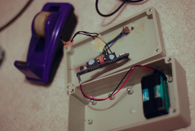
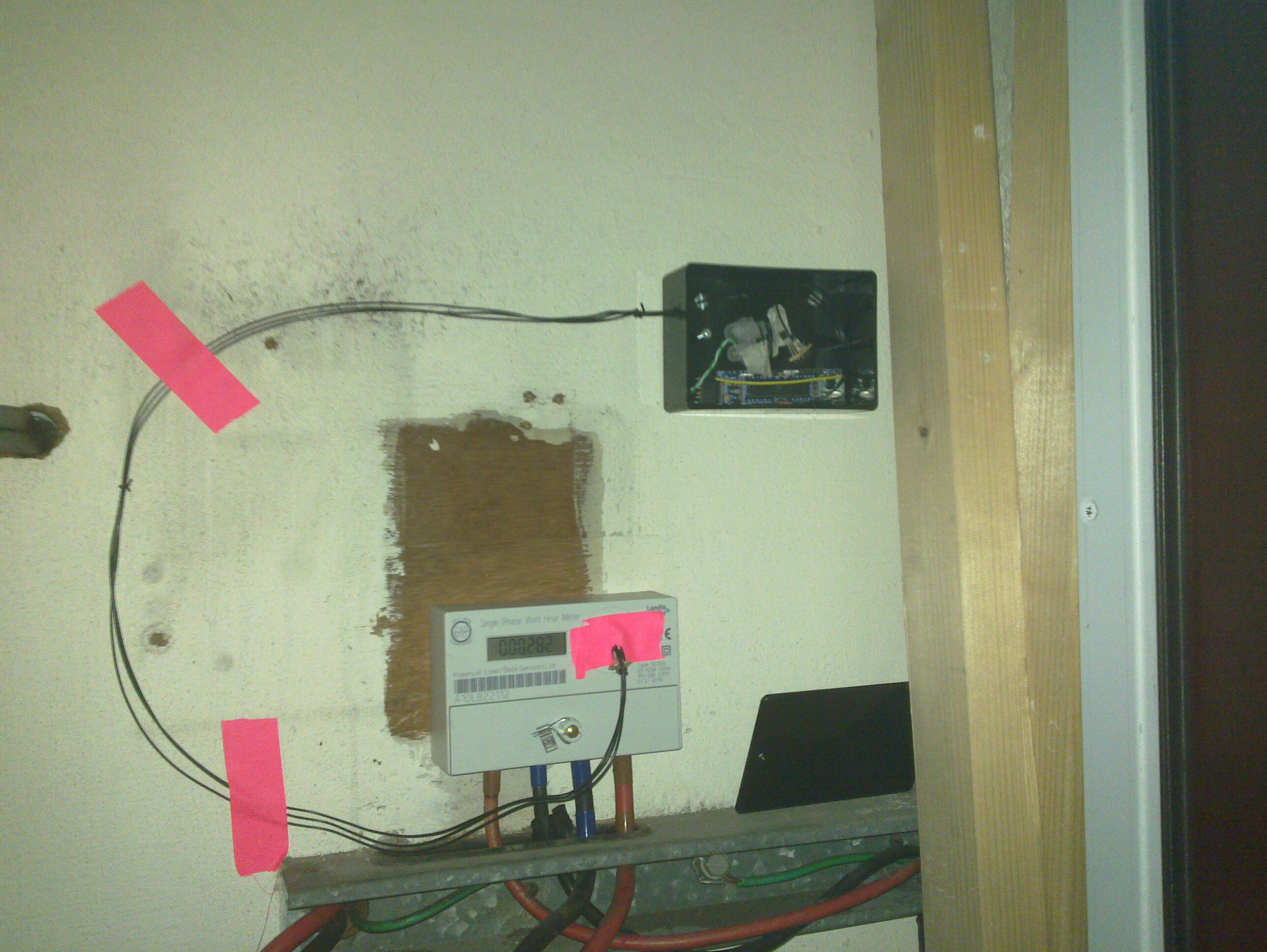
The Power Monitor is constantly looking for Led flashes from the
House’s electricity meter. Because these pulses are essentially
random, and don’t last very long, the node must constantly check the
phototransistor. This translates to the node being on full blast
almost all of the time, which sadly means hooking it up to an
external power source. This node also has a temperature sensor on
board.
Pictures
Every one loves pictures, so here are some of the nodes in place.
Here is the supposedly waterproof case for the outdoor temperature monitor. The light sensor is taped to a hole in the top of the case.
This is the power monitor, with some sexy camera tape. Using solid, single core wire is really not great for external sensor connections.