Its been a while since I’ve had time to write anything here. Moving house is difficult, renovating first is even harder. Merging your life’s possessions with someone else’s into house that’s clearly too small harder still, doing it all with shingles: Yorkshire level of hard, down’t pit etc.
Frivolities aside, I was doing some research into cheap pressure sensors. One of my friends was telling me about a anime he was watching. In this cartoon some bloke had rigged up his floor to detect weight, in an effort to detect people with invisibility cloaks on. We were debating whether this could be practicably done with today’s technology.
After ruling out suspended floors, peizo sensors, exotic strain gauges, I suddenly remembered about capacitance. Quoting from wikipedia, this is what a capacitor looks like in schematic form:

Where:
C is the capacitance, in farads;
- A is the area of overlap of the two plates, in square
metres;- εr is the relative static
permittivity (sometimes called the dielectric constant) of the
material between the plates (for a vacuum, εr = 1);- ε0 is the electric constant (ε0 ≈ 8.854×10⁻¹² F m-1);
and- d is the separation between the plates, in metres.
Basically the closer two parallel conductors are together, the greater the capacitance (Roughly true, charge leaking across the gap between the plates ruins the capacitance, hence why you need and insulator between the plates).
Well that’s great, but how do I measure Capacitance?
Not directly is the answer. Measuring capacitance directly is a bit challenging, timing how long it takes to charge/discharge is much easier. Its time to introduce Time Constants
This image taken from John Hewes’ excellent Electronic Club Explains what a Time Constant is.
 A Time Constant is the time it take a capacitor to reach 69% of the incoming voltage. You will note that the curve is exponential, and the voltage will never reach 9 (well in theory….) The formular for working out the time constant is wonderfully simple: Time Constant = Resistance * Capacitance So if C = 1 Farad, and R = 1 ohm, it’d take 1 second for the voltage across C to reach 5.8ish.
If putting two metal sheets separated by something both squishy and non conductive on the floor. Then if we wire up a resister of a known value and a power supply of a known voltage, we can deduce the varying capacitance by measuring the time it takes to charge the capacitor to 69% of the supply voltage.
Ahh measuring time and voltage from a micro-controller is simple!
Indeed all you need is an Analogue to Digital pin and a way to discharge your capacitor quickly. It turns out some lovely person has created an Arduino capacitance library here which makes the whole process wonderfully trivial.
Experiments
To test the theory, I decided to build a dirt simple test rig. It consists of three layers of cling film separating two layers of aluminium foil: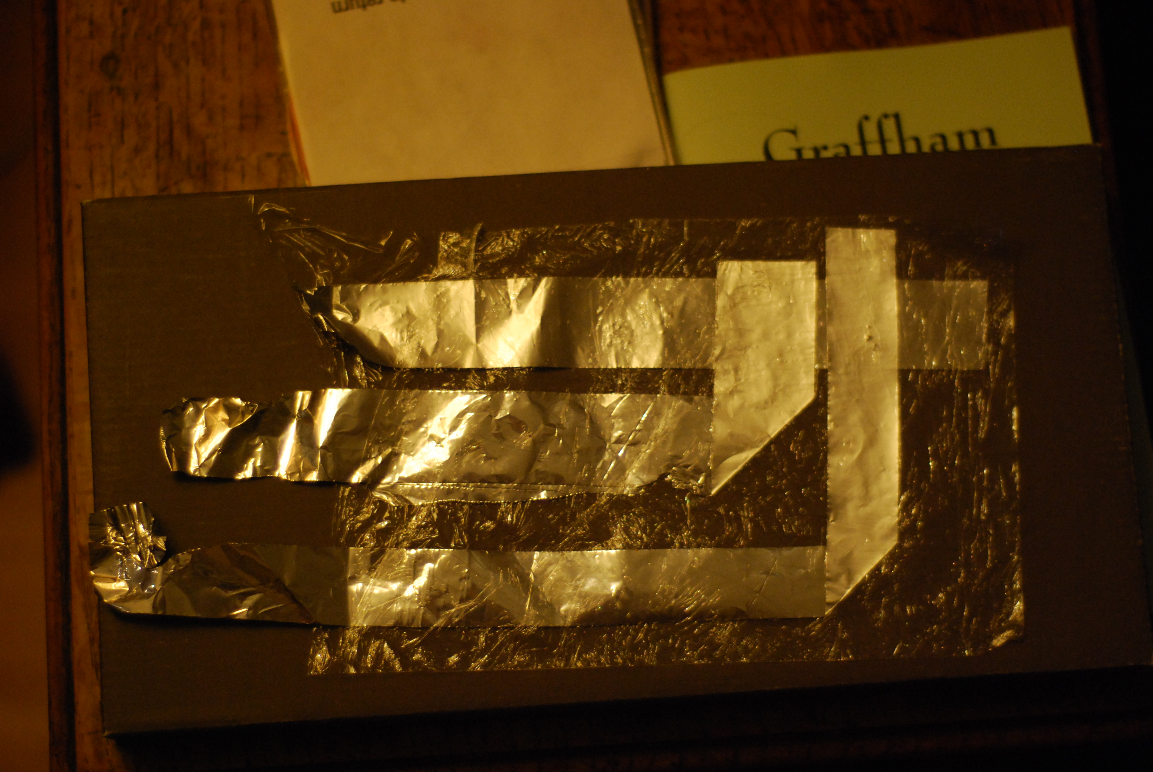 This is the prototype Fattie Measurer™. The electrode at the top of the picture is placed on a cling film substrate, which is then covered by another layer of cling film. The second layer of electrodes are placed directly on top, and held in place with the last layer of cling film.
After attaching the test rig to a LCR meter the readings were as follows:
- Unloaded capacitance: 400 – 600 pico farads
- Loaded(12 stone ~ 76 kgs): 20 – 60 nano farads
Which is a nice healthy difference. If a higher capacitance is required the intersecting electrode area can easily scaled up.
Further steps:
As an experimental test rig, the prototype performed well. However its not really that durable and doesn’t have uniform electrodes. There are also issues of scale. If each electrode takes 1 second to measure, then it will take 16 seconds to scan a 4×4 grid, one at a time. it will take 64 seconds to scan a 8×8 grid.
There are other tweaks that could speed things up. The approach I used in the test rig means that I can only really measure one area at one time. However I’ve not tested this.