I am a fan of Accutron watches. I have a number, including one that uses a quartz crystal to regulate the time keeping. The tooling required to make the index wheel was impossibly advanced for the time. The size of the teeth used in the main index wheel is tiny. You can only really see them clearly under a microscope, they are about the same size as a human hair (don’t quote me on that, but they are bloody tiny.)
I know I don’t have the skill, training or patients to make a small enough movement my self, But I’m reasonably sure I could make a clock using the same principle. All be it with some important modifications. There are some previous attempt from other people. This one uses a seven segment display, and this one has a nice circuit diagram that I wish I had found earlier.
The previous art is very nice, but not what I want. I have a tiny “master clock” which was originally designed to be installed in a telephone exchange. This gives out a pulse every 30 seconds, which is used to drive a solenoid based “slave clock”. The master clock has a wonderful musical quality to it, as you can sort of hear it here. (mine is half the size and has a faster pendulum.)
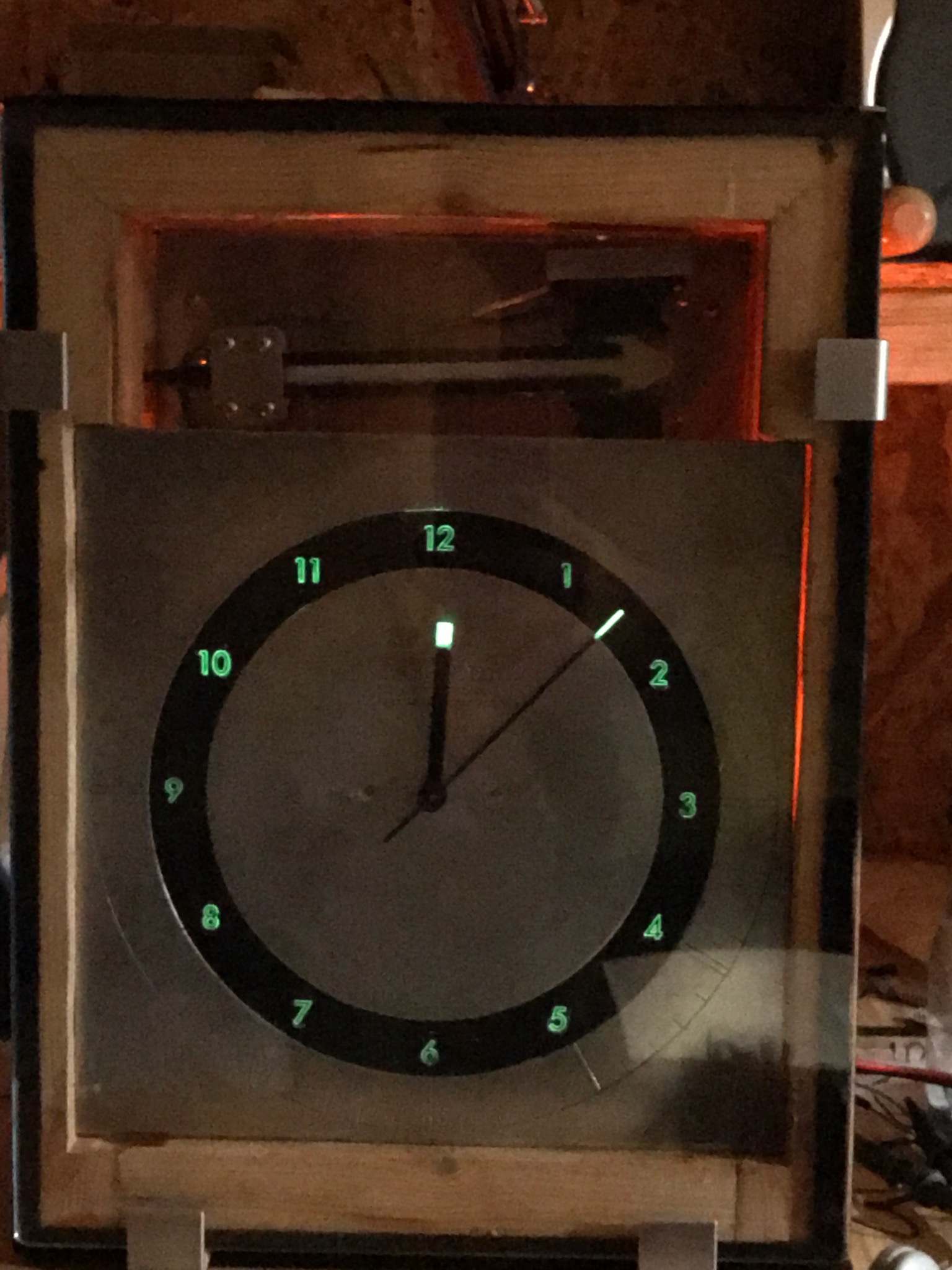
No, What I want is a nice sector dial clock, with some excellent glow in the dark numbers, with the tuning fork “mechanism” is full view. However I’m not going to drive the clock hands mechanically. I don’t have that kind of skill, either in 3d design, or machining. So I’m going to cheat and drive everything electrically.
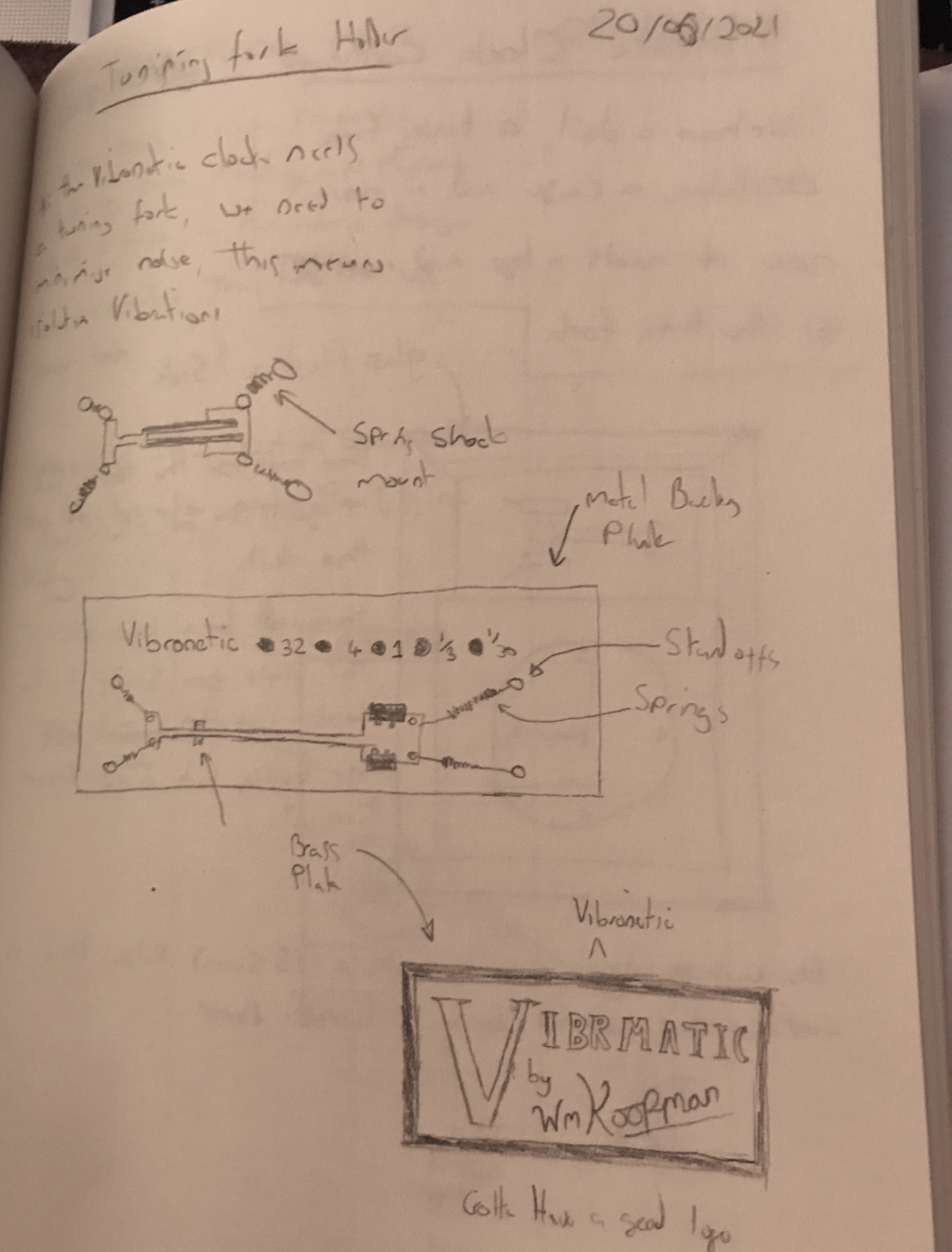
Design Drawing
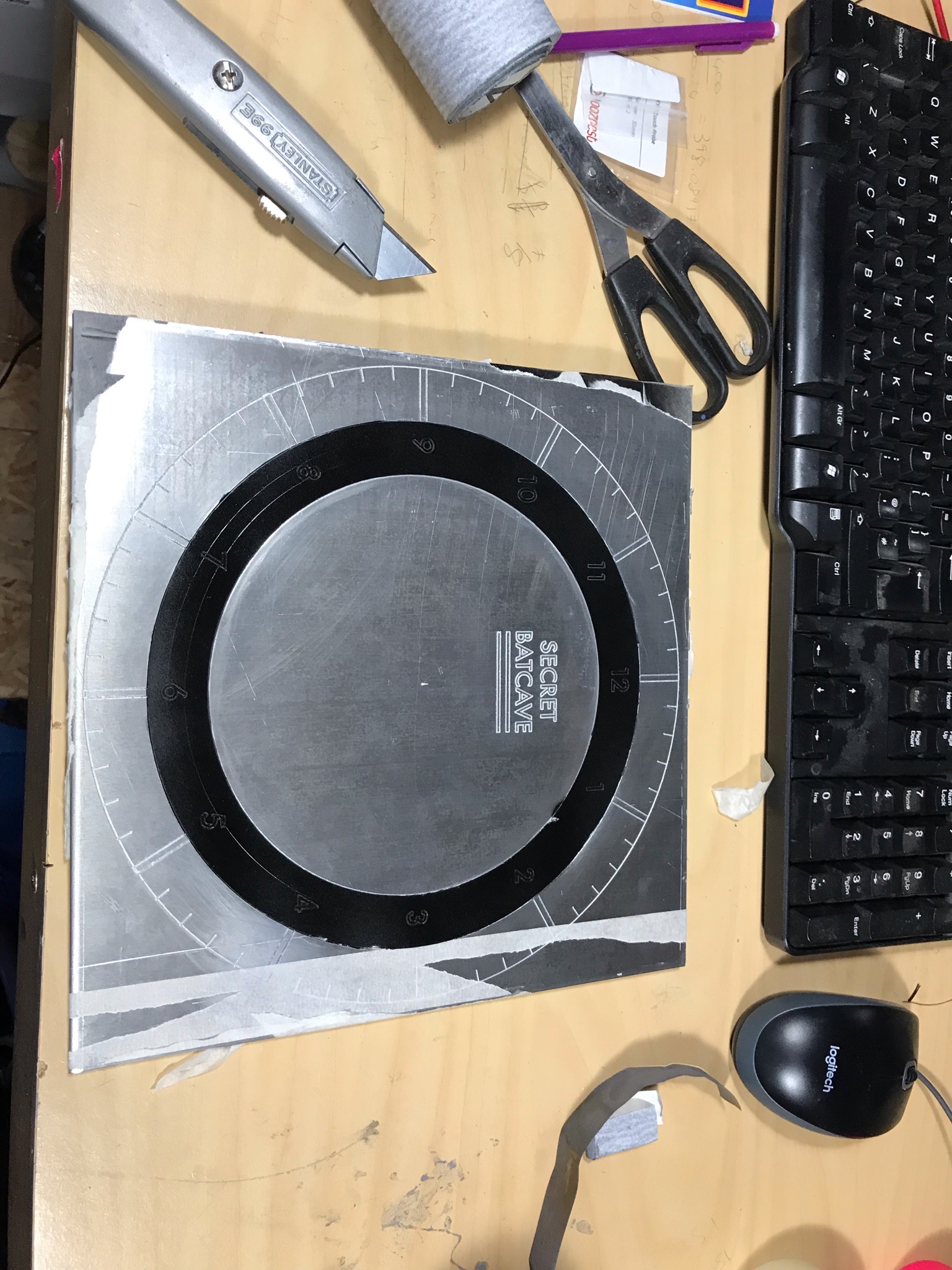
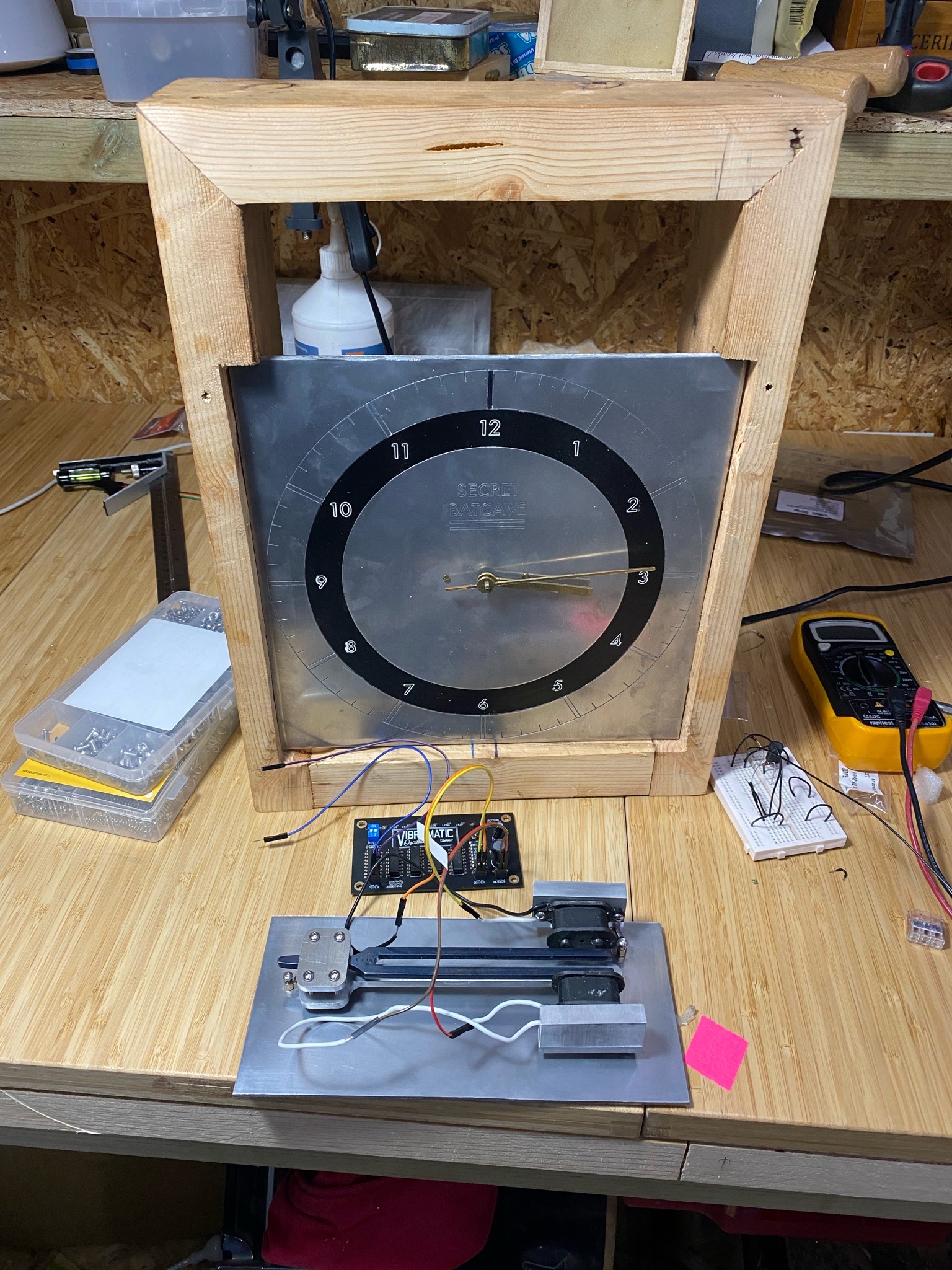
The Build: Clock Face
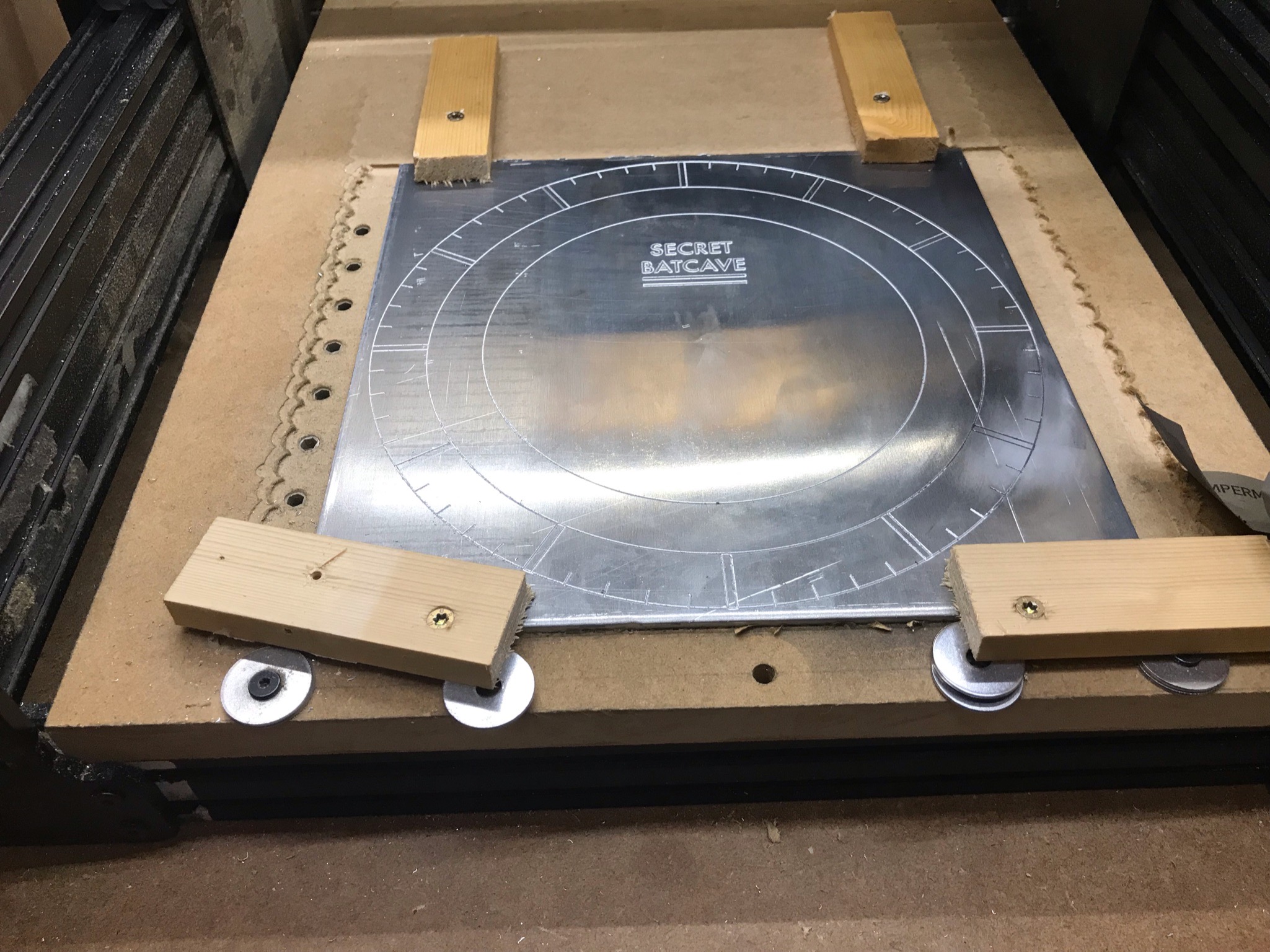
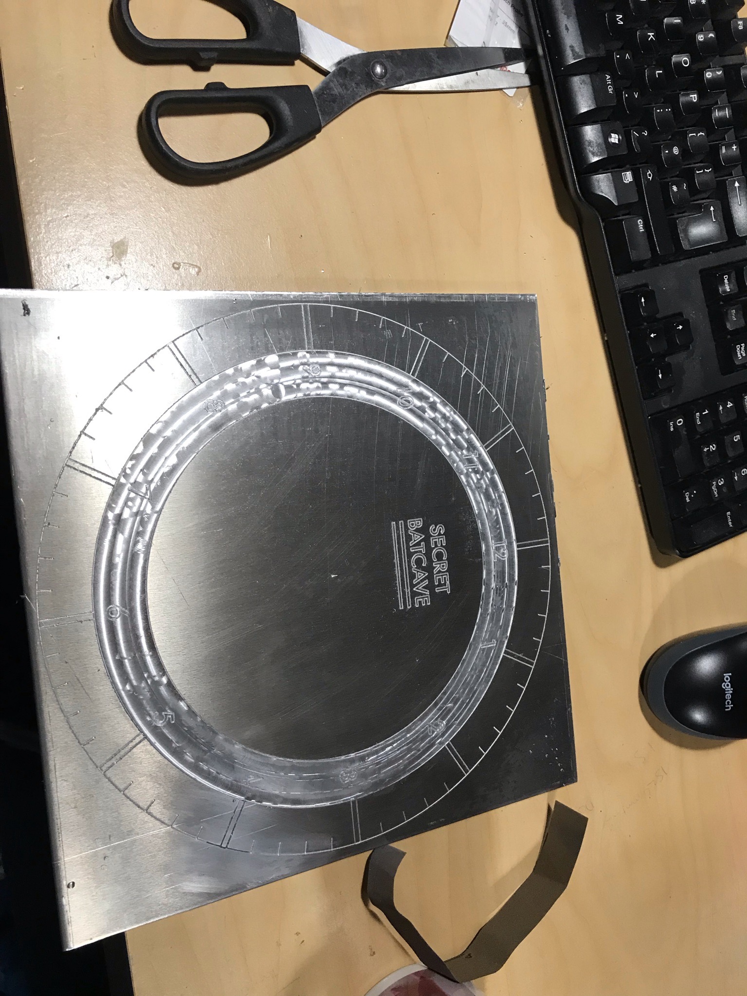
The clock face is the first thing you should see, so it makes sense to have a go at it first. I bought a slab of 5mm thick aluminium. It’s cheapish, strong, but not too strong to be a pain in the arse to cut.
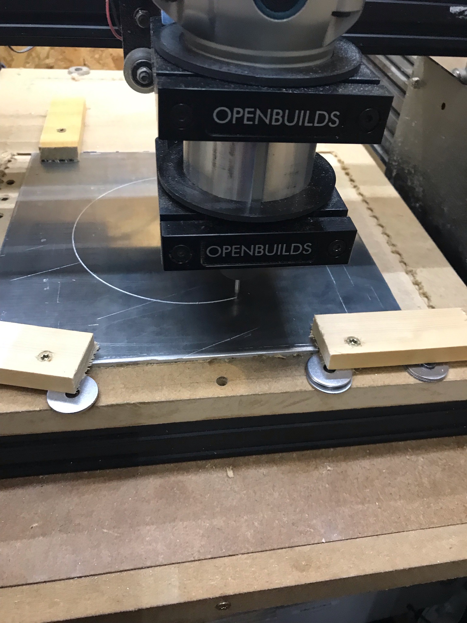
Cutting the first contour on the outside of the dial. I’m using a 60 degree engraving bit, because its robust and simple to use. Work holding is important to get right here. I had to re-face the baseboard to make sure that the aluminium plate remains as flat as possible. Because the workpiece is so large, I’m having to use nasty half arsed clamps to keep it in place. Protip: don’t do this.
I was lucky that the aluminium plate was flat. Otherwise I’d have to face and finish the plate as well before I engrave it.

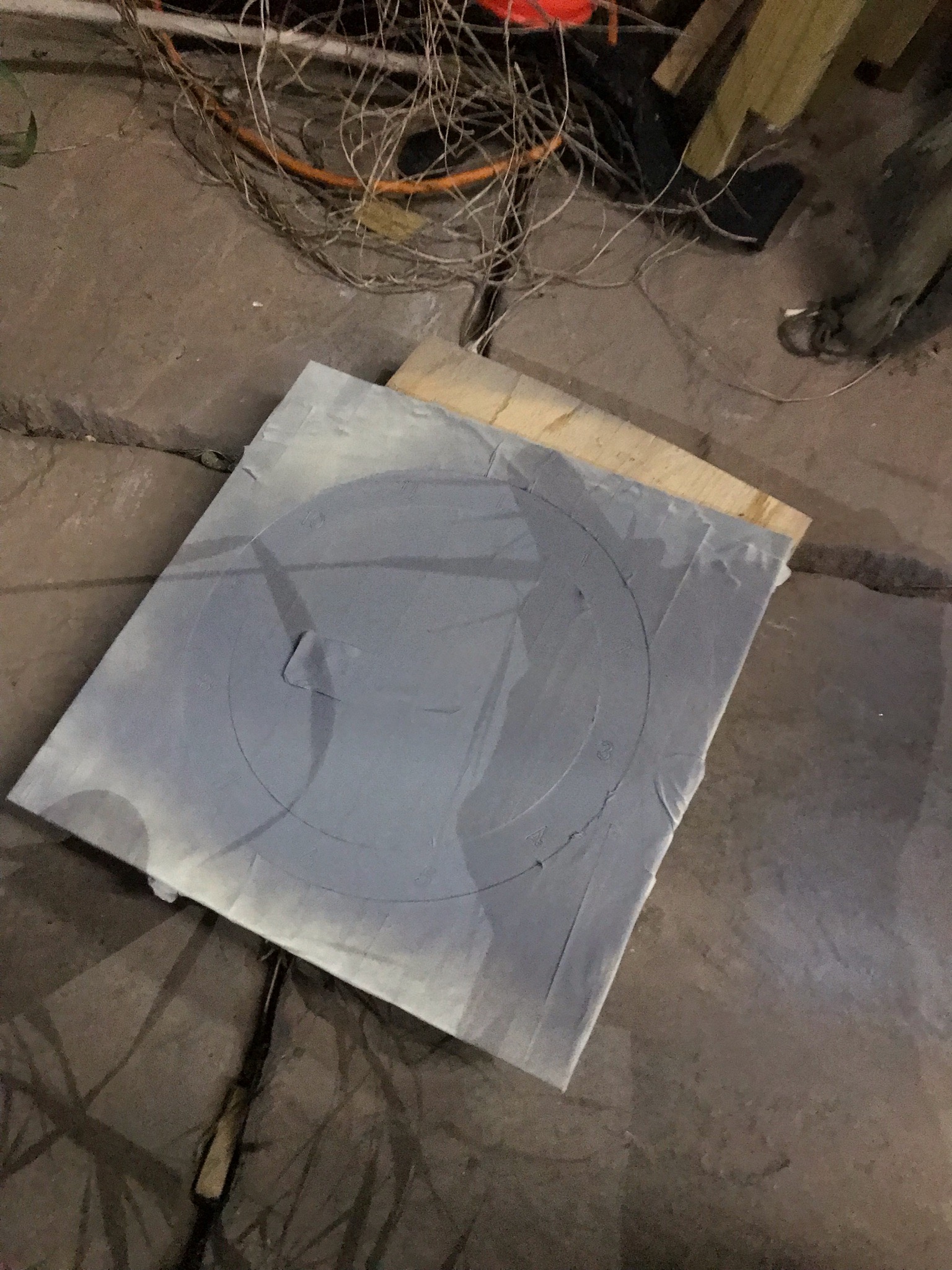
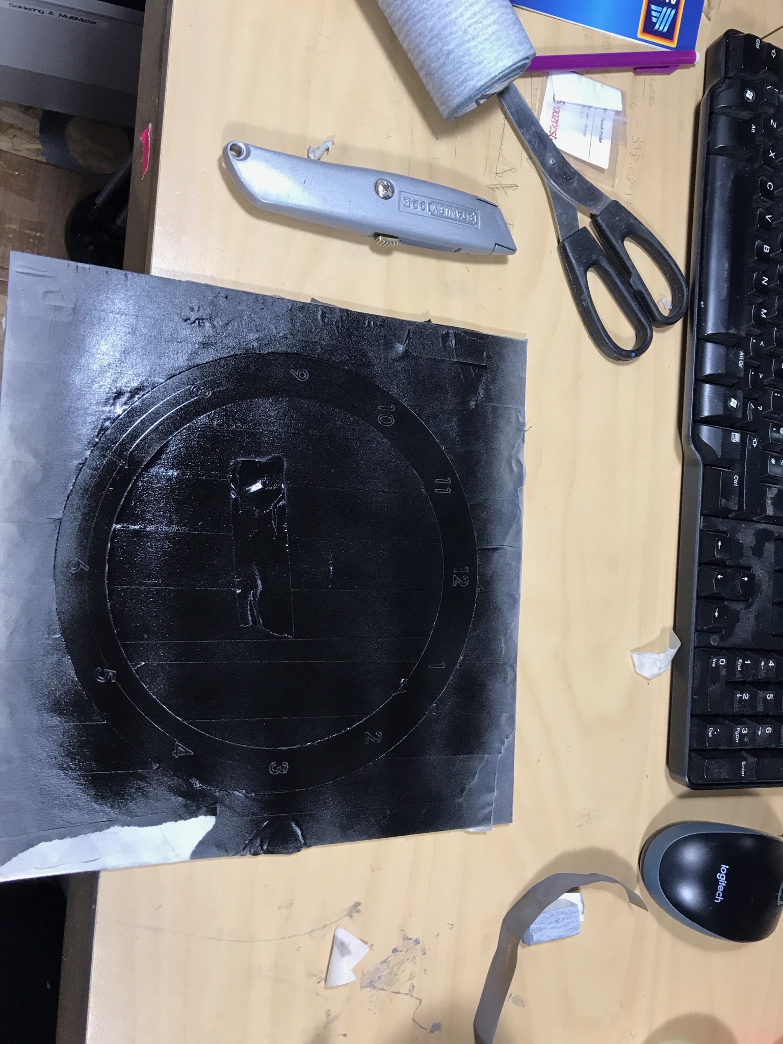
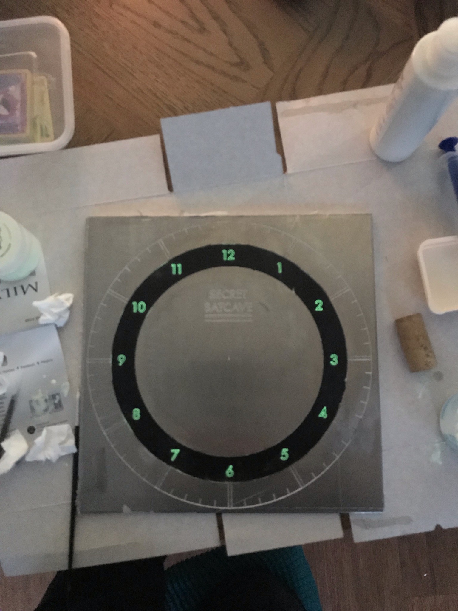
Now, the next step is applying the paint. Its a right pain in the tits. You need to mask off everything apart from the number pocket.
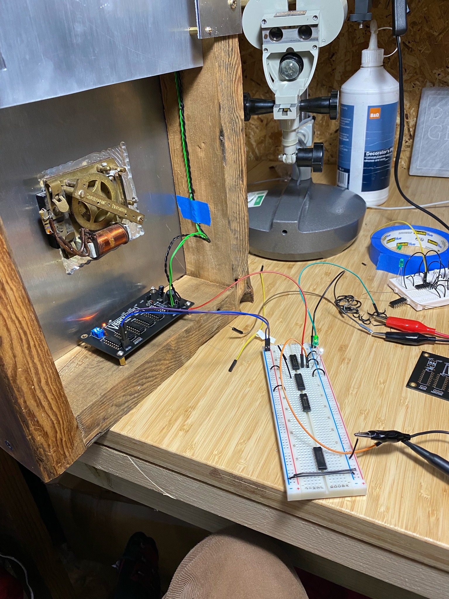
Prototyping the tuning fork oscillator
The basic principle is to create a feedback loop between an electromagnet, a tuning fork, and a sensor of some sort. Kris comes to the rescue here with this video and diagram:
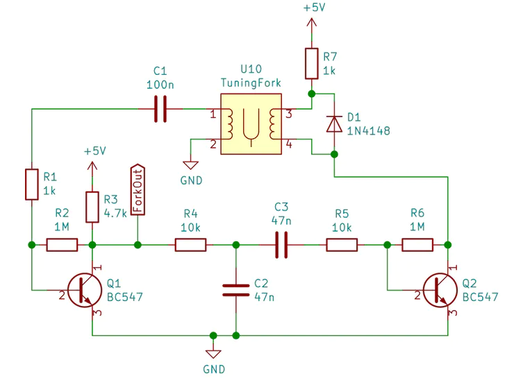
Her circuit is far more elegant than mine, instead of transistors I opted for an Opamp, this is because I was experimenting with winding my own coils to start with. In essence my coils were rubbish, and couldn’t generate enough current to trigger a transistor. I probably could have used a darlington pair, but that’s beyond my analogue skill level.
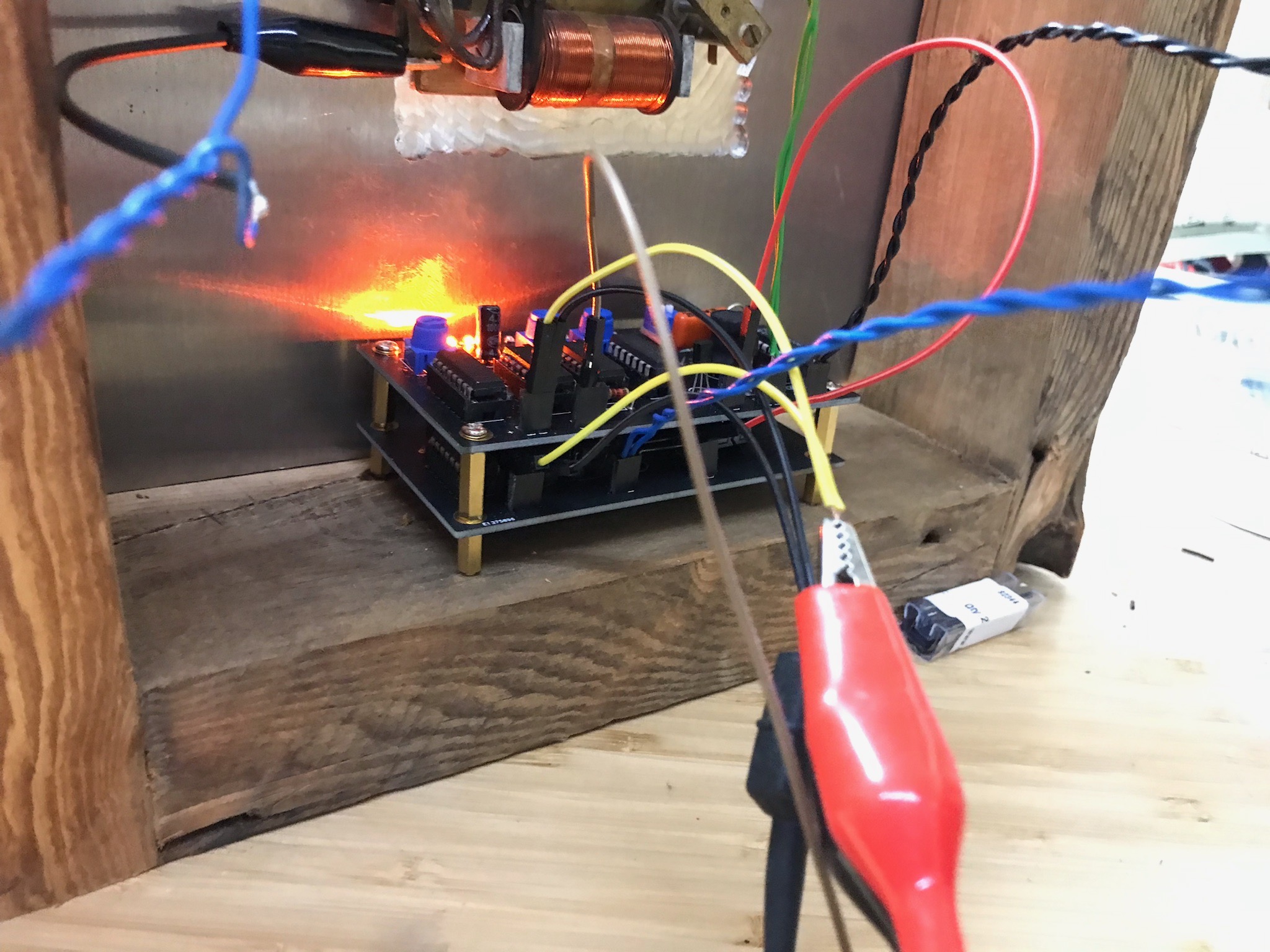
Here is my test setup. This allowed me to fiddle with the various coils that I was trying. Because I couldn’t get Kris’s technique of using inductors to work and my own coils were trash, I swallowed the expense and went with pre-made coils. The ones I settled on were Bass amp Guitar pickups. Solid, beefy, if a bit ugly.
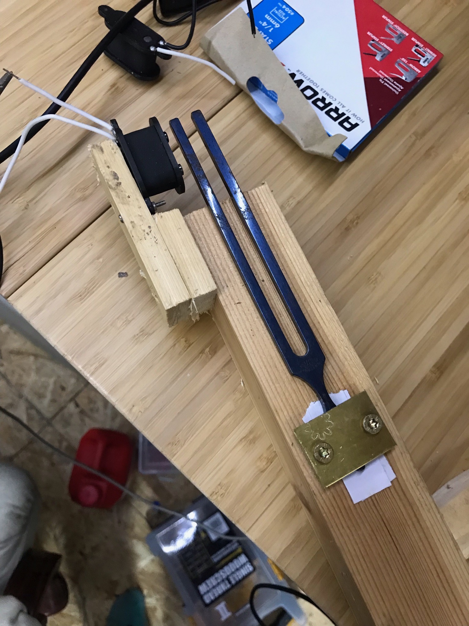
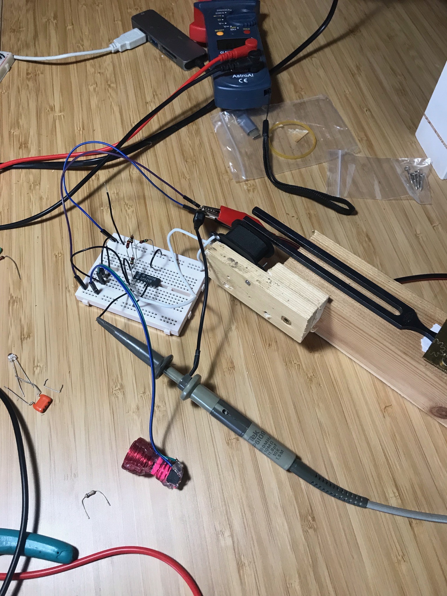
Here you can see my sad attempt at a drive coil, it’s the mass of red tape at the bottom. The pickup is next to the tuning fork. I was reluctant to send power through the pickup as they have permanent magnets that would (I thought) get blitzed. However the home made coil was never powerful enough to driver the tuning fork.
I suspect it didn’t work because of two reasons: 1) its shit, 2) I didn’t match the impedance properly. I have forgotten most of my analogue electronics theory. If I’m honest I never really grasped it, it all seemed a bit like mysticism really.
Here we have the first self sustaining oscillation. It’s not at the rated frequency of the tuning fork(256hz). I bought this fork second hand, so I assumed that it was out of tune for some reason. I re-tuned it by ear, playing against a known good source. However whatever I did, it was always self oscillating flat. Turns out there is some magnetic drag that is lowering the frequency that the fork oscillates at. Worse still its not a static offset, it very much depends on how powerful the magnetic field is.
Counting Logic
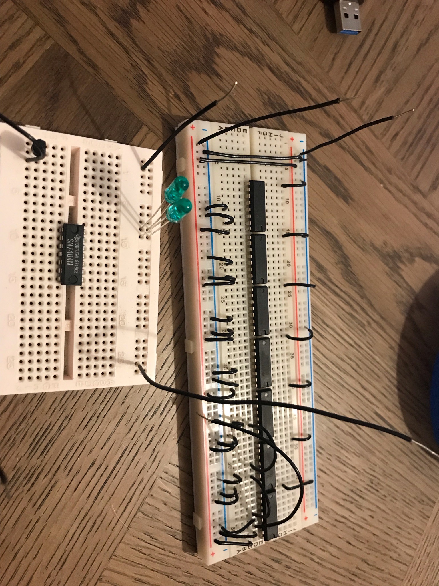
I didn’t want this to be yet another microcontroller project. I’m middle aged now, so I need to do things “old school”. For me, this means going back to A-level electronics and using 7400 series discreet logic. The first approach was using a bunch of decade counters. The basic mode of operation is:
- Set the tuning fork running
- Turn the output waveform into a square wave
- divide the tuning fork frequency (supposedly 256hz) into 1hz.
- divide 1hz into one pulse every 30 seconds.
Basically we want to count to 7680, then energise the solenoid on the “movement”, the thing that moves the clock hands.
Always do integration testing.
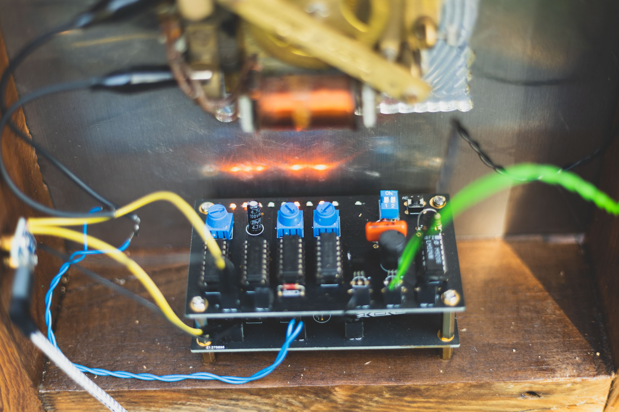
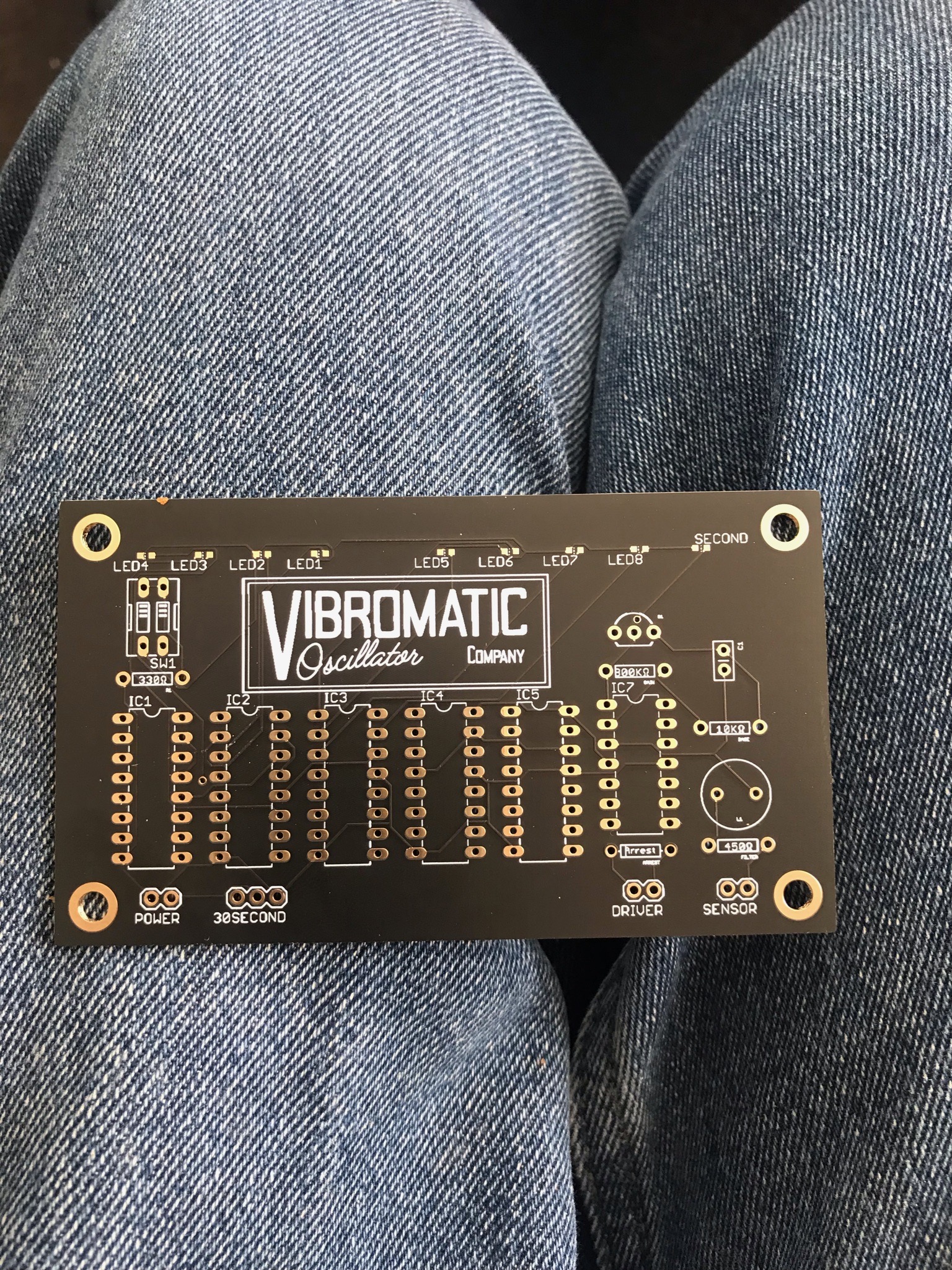
This is the stage of the project where things start to go wrong. As I’ve said before, I’d noticed that the tuning fork was not oscillating at its “free running” frequency. Instead of embracing it, I chose to ignore it and just carry on. to that end, I made a loverly looking PCB with a great logo:
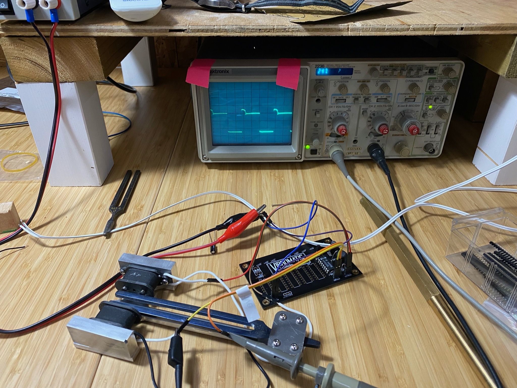
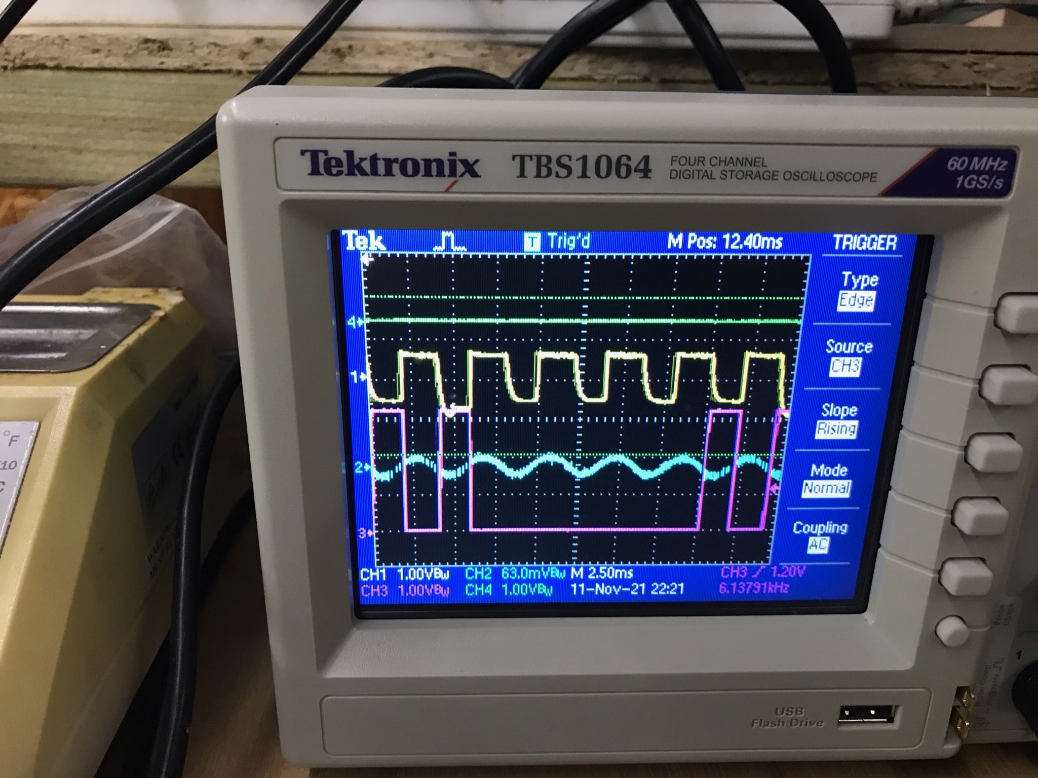
You can see here that the oscilloscope is showing that its running at 247hz. Again, you’d think that I would pause and re-calibrate here. But no. I’m just going to blunder on and try and physics my way out it of.
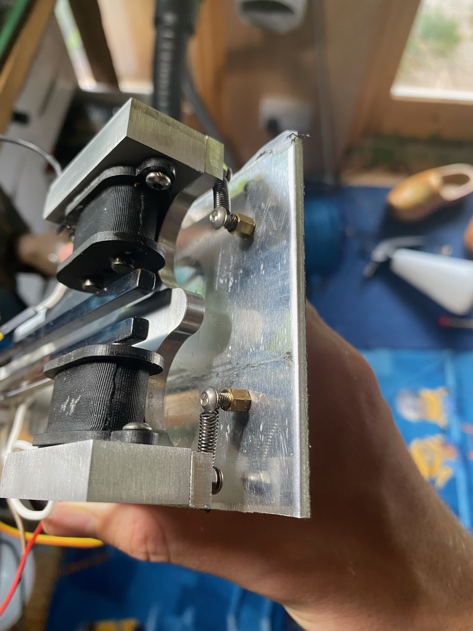
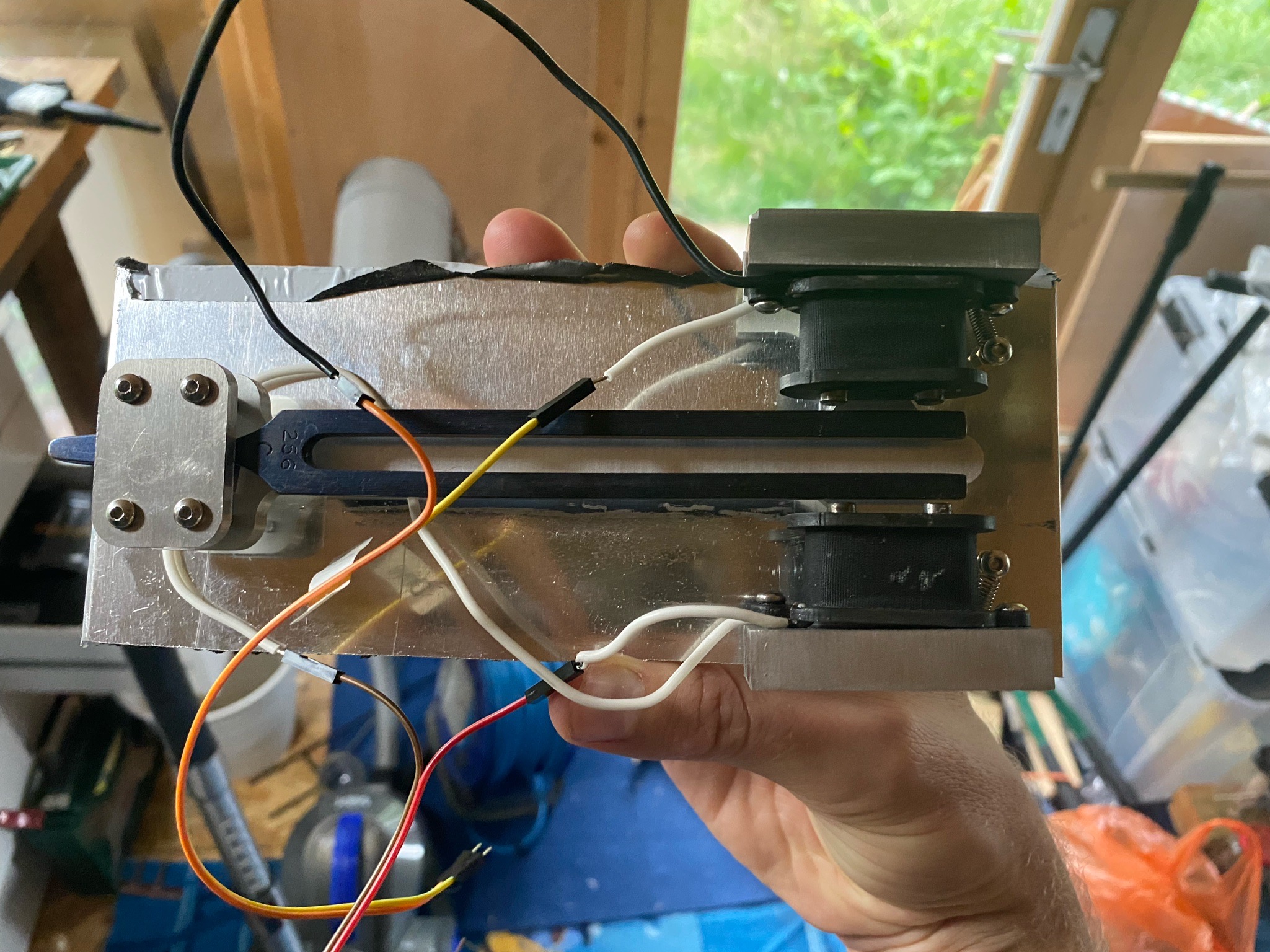
Shockmount
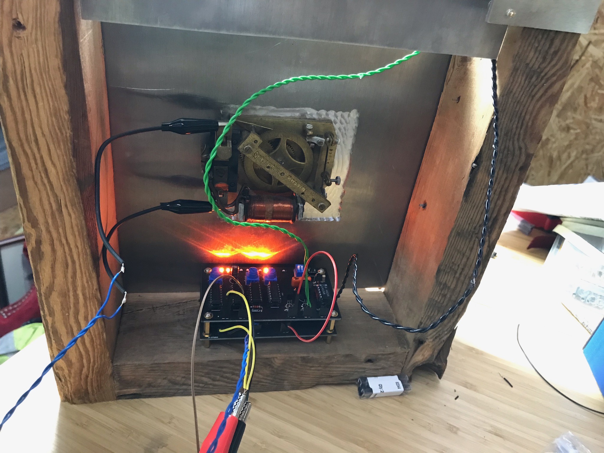
A lot of the prior art say mostly the same thing: it looks great, but bugger me it don’t half make a racket. To get round this I’m using an age old sound engineering trick: the shock mount. You can see how they work here. I’ve made sure that the holder is much heavier than the thing moving. I don’t want it to act as a floating soundboard, sapping efficiency.
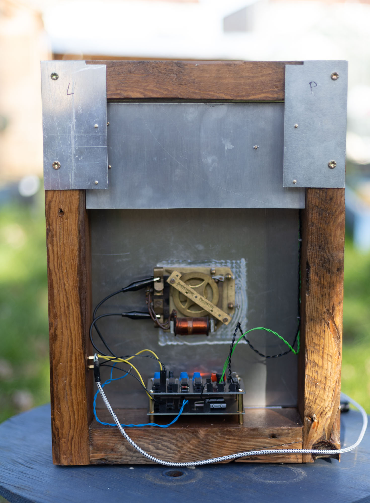
Case assembly and fitup.
I am lucky enough to have recently had a loft conversion. My house is 1930s, so about ~90 years old. I’m not boasting, but it means there are a bunch of roofing timbers that are going to be thrown out. So I decided to use beefy lump of what might be Norwegian spruce to make the case. At least this way, when people point out how “rustic” the case looks, I can say its got Terroir.That’s my excuse, and I’m sticking to it.
Here you can see das blinken lichten. The noise is the fan of the oscilloscope, not the tuning fork. This is where it hits me, that I’ve made mistake in pushing ahead. The counter isn’t counting properly, because I have cocked up the reset logic. I’ve also hardwired the wrong number to count to. Balls
Using a proper counter
So I spend many more days trying to crack this, and decided to use a 14 bit counter. This has a few drawbacks, as it doesn’t break out bit 2-4. This means that the total number I’m going to count to needs to not use those missing bits.
I also need to make a pulse extender/limiter. This is so that I can control the length of time the solenoid is powered on for, without affecting the counter.
Into Madness
Now that I have something that looks like it might actually work, I need to test it. As you can hear from my swearing, its not going as it should…..
As you can hear, its not going that well (caution swearing). The reason is actually quite simple. I feed the overdriven opamp signal into an inverter to create a nice square wave output. as you can see from the video, the oscilloscope says its a nice clean square wave, but the counter says that there are 3.7 times more pulses than there should be. It turns out that the opamp/coil/transistor is kicking out harmonics when its turning off the driver coil. This is sometimes around the undefined voltage level of the inverter. This causes it to swing back and forward between 1 and 0, triggering the counter.
It took me a good month to figure this out, I found it by accident when fiddling with the trigger settings.
The solution is to use a schmitt trigger, as it has hysteresis that overrides the CMOS “wobbly voltage” zone. You can see the sloped output here, after I’ve been playing with the offset voltage.
Endgame
IT WORKS AS EXPECTED. well not quite, The remade PCB is not as good looking, but crucially is triggering the solenoid every 15 seconds. This means that I need to make a correction PCB/power conditioner. The solenoid would cause a massive voltage drop and make the whole thing unreliable. So I hastily made a daughter board that has two huge supercaps, the flipflop divider circuit, and a darlington pair/diode arrestor to drive the solenoid.
Sexy Shots