Raspberry pi controlled heating
Or “Why on earth didn’t you just buy a thermostat?”
Description of the problem
We moved into a 1930s house a few years ago, with that comes a few good things: enough space to build a shed, no leasehold silliness. However that does mean that we do have to fix our own problems.
One of those problems is heating. The house was designed to be heated by 4 open grate coal fires. This means lots of air bricks. What it has in “charm” it lacks in insulation. To the point where my shed is significantly better insulated than the house.
As a sticky plaster we have an RF thermostat, which means we can move it from room to room to adjust as required. However, dear reader, we lost the thermostat. It still works, but we cannot find it.
I ordered a Salus RT500rf wireless thermostat from amazon, however the seller did the old bate and switch, sending the £60 cheaper wired thermostat instead. Its a shame as its a great 7-day thermostat with boost function. Anyway, that was sent back, now what do I do?
TL;DR: We physically lost the RF thermostat. Amazon screwed us over, lets build one.
Design Requirements
It must be:
1) Simple
2) Reliable
3) Pass the wife test
4) Controllable via a mobile
Now, there are lots of opensource house automation things out there. However, thats a lot of overhead, most of which wont pass the wife test.
I could pledge alliance to one of the feudal over lords, but that seems a little short sighted.
So therefore one must exercise a little Ego massage and build a system from scratch. Well, not scratch, there is already a lot of infrastructure lying about.
Infrastructure I have lying about
Being a good sysadmin, there is a surprisingly large amount of useful bits attached to the house:
1) A Comprehensive wifi network, that reaches the whole house, shed and garden
2) An abundance of temperature sensors
3) A centralised database to which they all feed
4) A means to share calendars with the wife
Thus we have most of the building blocks required to build a fancy smancy internet thermostat.
Controlling a boiler.
There are two ways to control a boiler:
1) A simple relay to control the on/off thermostat input
2) An OpenTherm interface which allows significantly more control.
Option 1) only requires a 240V AC relay, which is fairly cheap and easy to procure. Not only is it cheap, its pretty simple to programme.
Option 2) requires a more expensive interface board and a lot more brain power. There isn’t really a turn-key solution to making a simple thermostat. Because there is much more control, there is a far greater risk that I might break the boiler by asking it to do something its not designed to do.
So, like a real pragmatist, I am going to try option 1 first, as that sounds far more simple.
The software
The software is pretty simple. Its a python script that grabs a shared calendar using icalevents. Each event’s name is just a integer, which corresponds to the desired target temperature. The script then compares the target temperature with actual value reported by the sensors. If the sensors report a colder temperature, it turns on the relay, vice versa if its warmer.
To make sure we know what is happening, the script also emits graphite metrics which are displayed on a grafana dashboard. This not only allows me to generate pretty graphs really easily, it also allows me to create alerts when something goes wrong. After all, you don’t you thermostat to fail in the middle of winter and not know about it.
The Dashboard looks like this:
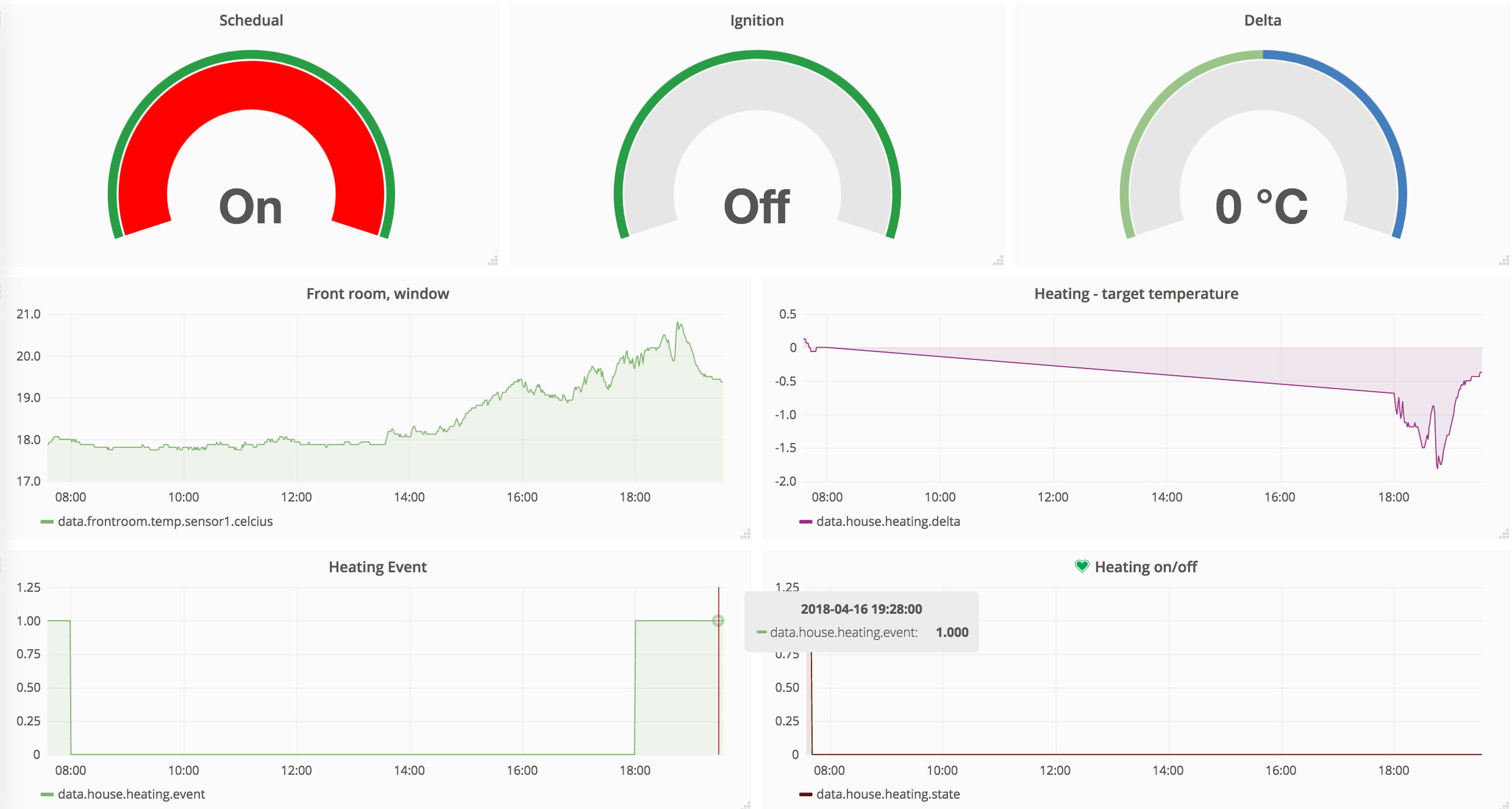
features/bugs
The most glaring feature is that this script must be run in a cron job style. It doesn’t hang around. This is because the icalevents library has some wonderful caching, which I wasn’t able to control properly. This means that if you don’t have a metrics system you’ll need to find some other way to figure out if the script is running or not.
As I’ve alluded to before, the script also poops out a number of metrics, Some are useful bits of information (Is the boiler meant to be running, the difference between the target and actual temperature, is there a calendar event), others are just for debugging. These don’t affect the running, but make it much more visible.
There is also Frost protection. This is critical if you live in a 1930s house with crap insulation (well, it won’t be crap for long, but thats another blog post) Frozen pipes are messy, so we want to make sure we avoid freezing. To that aim, if the temperature drops below 7 degrees, the heating automatically kicks in. This might seem a little extreme, but this winter it dropped to -10 degrees Celsius, well below blown pipe territory.
Github
I have put the code up on github however you will need to modify two things to make it work for you.
Hardware
The hardware consists of a single raspberry pi zero (no wireless…), a waveshare relay hat USB wifi dongle, a spare mains wall socket, and a mains to USB PSU. (you’ll see why its I needed a wall socket shortly…)
The reason I selected the Waveshare relay board is because its a 240v tolerant board with proper opto isolation. Why do we need to cope with 240volts AC? Because the standard boiler thermostat interface is raw mains. I assume this is historical, either way its not brilliant fun to deal with.
Complications
To add to the fun, there are no spare sockets anywhere near by, and as the boiler is in the kitchen, near a sink, I don’t want trailing cables. To over come this, I will need to install a plug on top of the boiler, allowing me to hide the Pi and various cables out of sight.
This is not as difficult as it might first seem, The boiler has lots of screw terminals, including for the mains input. I ran a spur from this. This also means that when the boiler is isolated, so it is the pi.
Installation photos
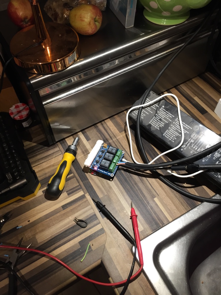
Mains voltage: hence the volt meter. You really need to make sure its all off before you even think about touching stuff
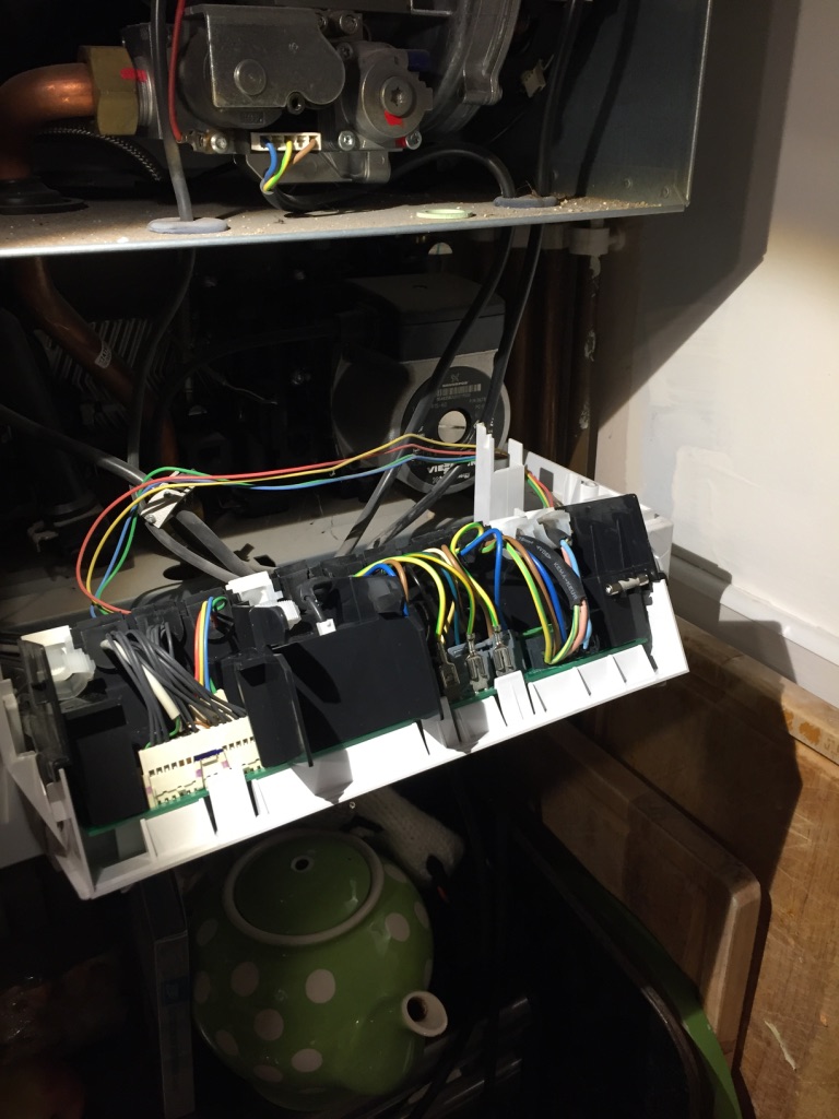
The finished wire loom. On the right you can see the tick black cable that leads from the Pi’s relay. On the left above the tea pot are the two mains cables, one coming in and terminating in the supply terminals for the boiler, the other leading off to the extra plug.
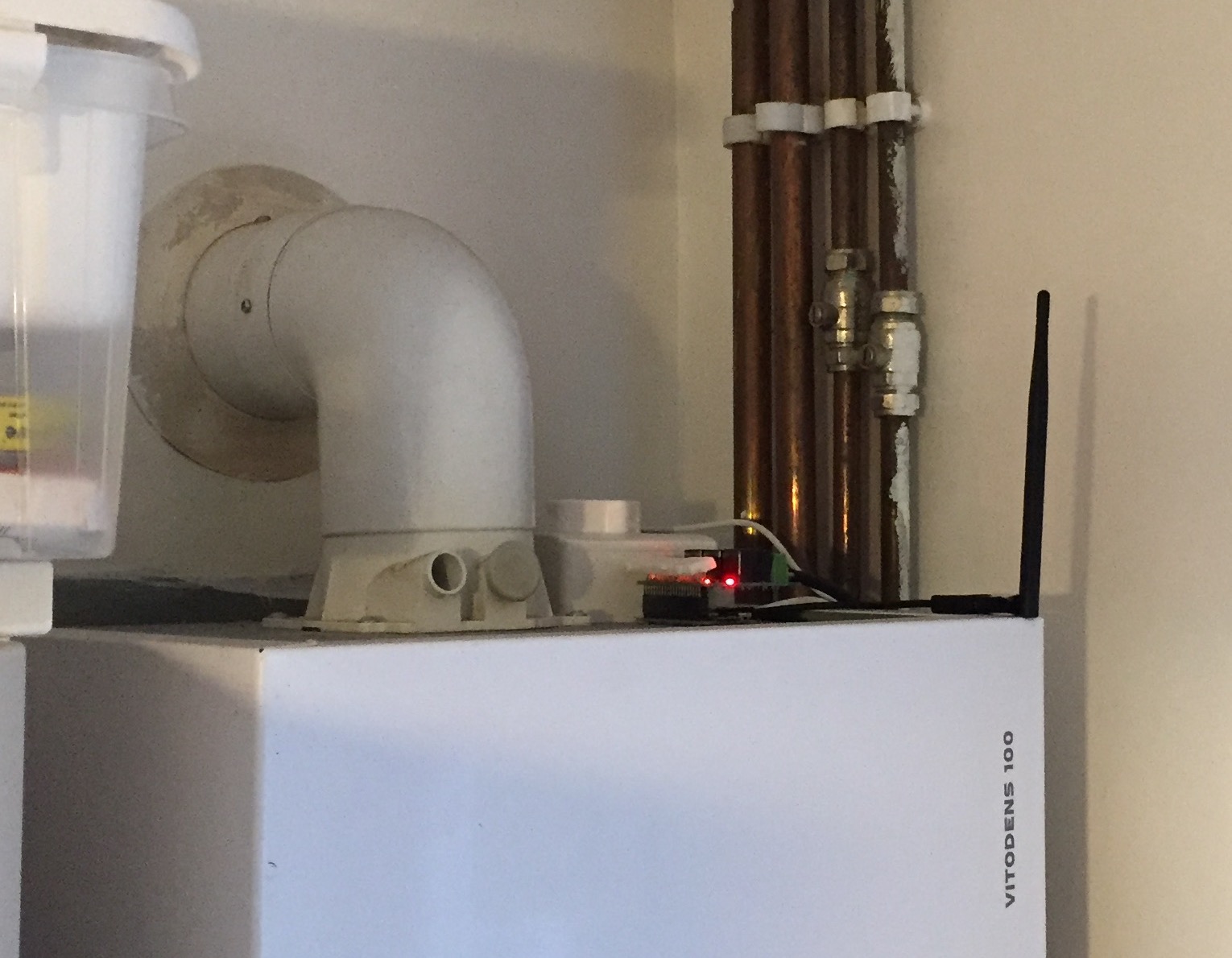
The Final installation. Note the red light, that the relay in the on position.