Fireflies in a Jar
Or how I learned to “love” tiny weeeny surface mount components.
The Brief:
In the run up to our daughter’s birth I wasn’t allowed to do any “frivolous” things. Anything creative had to be directed at the baby. I’ve been playing with the idea of flashy fireflies ever since my time in deepest darkest new york. The swap lands in august are blanketed with thousands of fireflies blinking away. So the idea was I’d create a jar of fireflies for my child.
There is lots of prior art with many different approaches. This is possibly a warning sign that I haven’t got anything new to add. However it was either keep my hands occupied, or doing one’s nut. The basic idea is that I’d make an insert for a Kilner jar that had a number of LEDs, a solar panel and a bank of supercaps. The hope is that it would last for her entire childhood.
One day she might learn to program it, and thus hopefully have a life with a small prospect of earning a living. (Although by the time she grows up programming might not pay the bills….)
The Design:
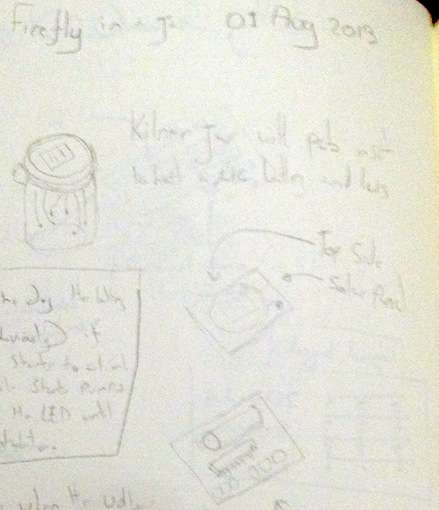
As you can see the original plan was to use a single supercap, however even if you use 20F caps they really don’t have enough juice for a decent show. After a brief prototyping I went ahead and bashed out a PCB. Seeed studios are a great cheap way to get your PCBs printed.
Behold! Version 1:
You can sort of make out the two 10 farad super caps. They rather dominate the entire thing. On top of the board is the 3.3v DC-DC converter from sparkfun. It does a wonderful job of stepping voltage up, rather bad job of holding the voltage down.
Sadly this meant of the charge we collected (around 3.5mah) around half of it would be burnt away by the voltage converter. Obviously this is very bad, end of version one.
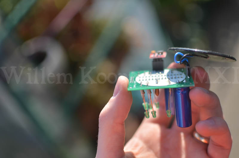
Avast, version 2!
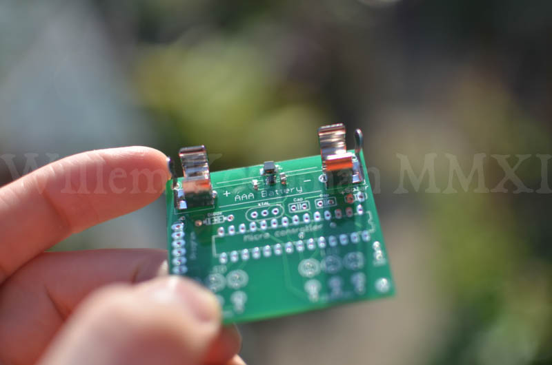
As you can see, it’s much neater. Both the power daughter board and capacitors have gone. Replaced with the LTC3525 and an AAA battery respectively. I considered doing this from the start, however I feared the surface mount. (Hence the title of this page.) Fortunately for me the wondrous jeelabs has done most of the work for me.
The hardest second hardest part of SMT is the designing. There are a multitude of different sized parts, which might do the same thing, however they could also be completely different. In normal electronics, resistors are mostly one size, caps another. With SMT there is an entire galaxy of parts in a myriad of obscure sizes. As I hinted Jeelabs have done most of the work for me by creating the AA board. JCW, Having studied the datasheet and selected the best combination of parts, all I had to do was copy and paste. (well as much as one can do that in Eagle.)
However, when soldering, not shorting pins together is exceptionally hard.. Online videos suggest one can use the “Drag method” however the pads are far to close, and the solder stop not well defined enough for this to work. The key to successfully soldering tiny parts is to use almost no solder at all. It’s incredibly easy to solder two legs together.
After three attempts (twice soldering legs together, once overheating the IC) I have a fully working PSU. Sadly is doesn’t perform as well as the jeelabs board. Another annoying draw back is the poor performance of the solar panel. It appears to only halfassedly charge the battery. A day of full sun yields about 5 minutes of run time.
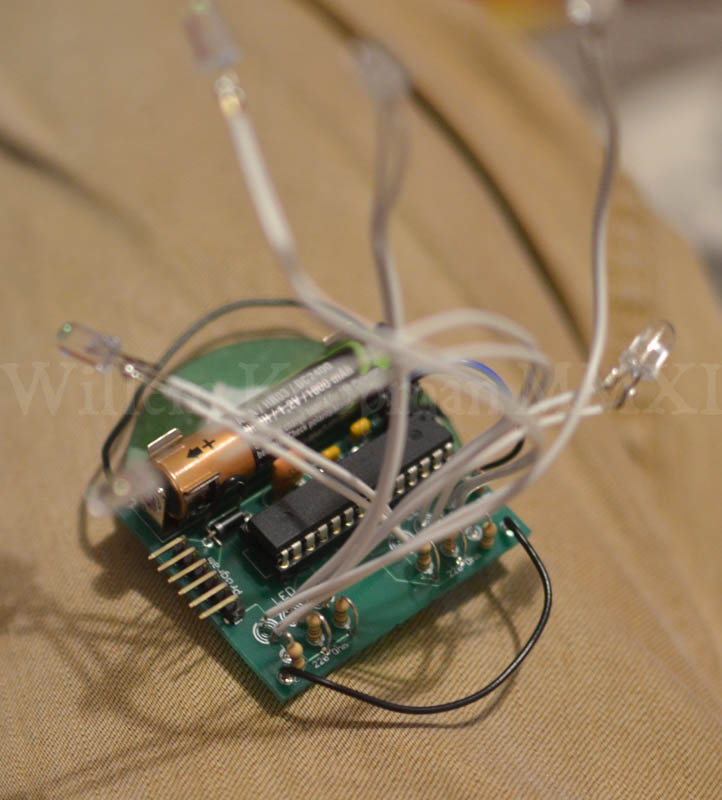
Looking at what was going on, it appeared that the battery was hovering around the cut off voltage, then sharply dropping. This meant that the battery didn’t have enough juice to get the arduino into sleepmode.
I placed a supercap in parallel with the battery to attempt to provide a short term reservoir so that the regulator would have enough power to allow the microcontroller to enter sleep.
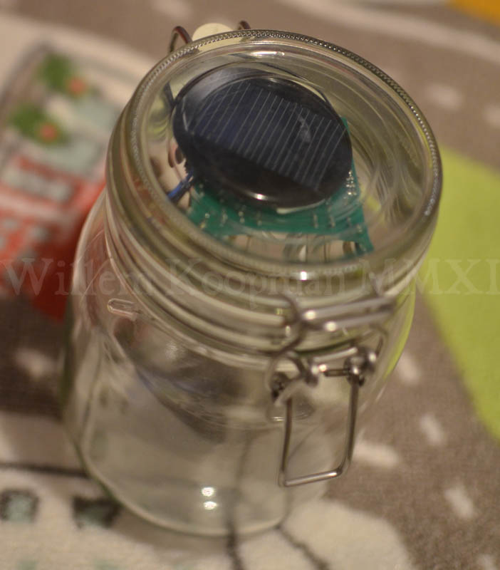
Photos:
Update:
Turns out its much more simple than that. The cut-off mechanism for making the microcontroller sleep was based on measuring the VCC line of the Atmel. As we’ve put a really nice regulator between it and the battery, it’s clueless as to the state of charge. This meant that the lights remained on too long and drained the battery far too much.
When the Sun comes back, the battery would charge past the strike voltage, the microcontroller would boot up, cause the battery to drain, and the whole process would repeat ad nauseam. As you can imagine it wastes lots of energy.
The solution is to use the solar sense line as a battery detector as well. I planned to do this, however in the PCB deisgn stage Eagle told me that I was holding it wrong, and two of the pins of the microcontroller we joined to the same thing.
Why this is improves things is because we can dive into sleep mode before the battery fails. This means that we never enter a state where we are hovering around the regulators strike voltage.
Update again:
The reason why the surface mount was so difficult to solder by had is because the soldermask accuracy of seeed studios is hilariously off. So I tightend up the mask, and shipped off a new order to OSH park. You can see the difference in a detailed review here The difference was most pronounced, soldered correctly first time!
The moral of the story, always make sure you have a decent solder mask.