I wanted to have a stock ticker, after seeing an article about how to value said mechanical marvel. I looked and thought: “Ooo! I’d like one of those, its like a teletype, but much smaller and cooler.”
Turns out the reason why nobody has one is because they cost >£4000 and rarely come on the market.
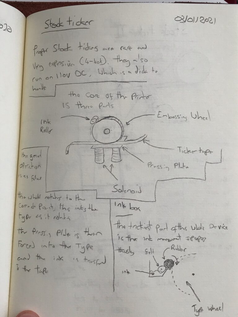
If you don’t know what I’m talking about, here is a picture:

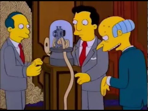
They are a striking, iconic even piece of late Victorian engineering. They have seeped into pop culture so much that they pop up everywhere, including the Simpsons:
If I can’t buy one….
I’m going to have to make one instead. The basic plan was to take
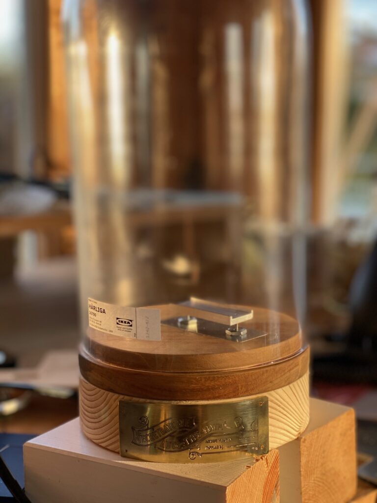
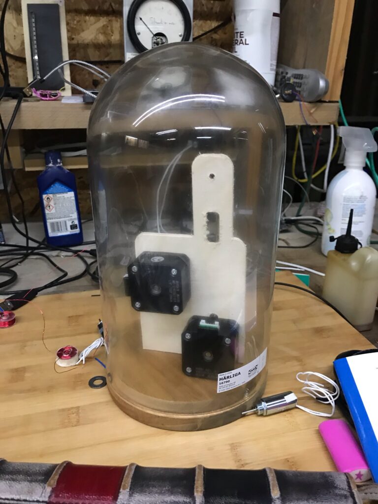
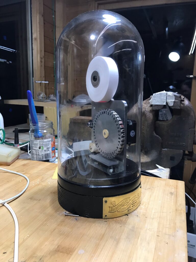
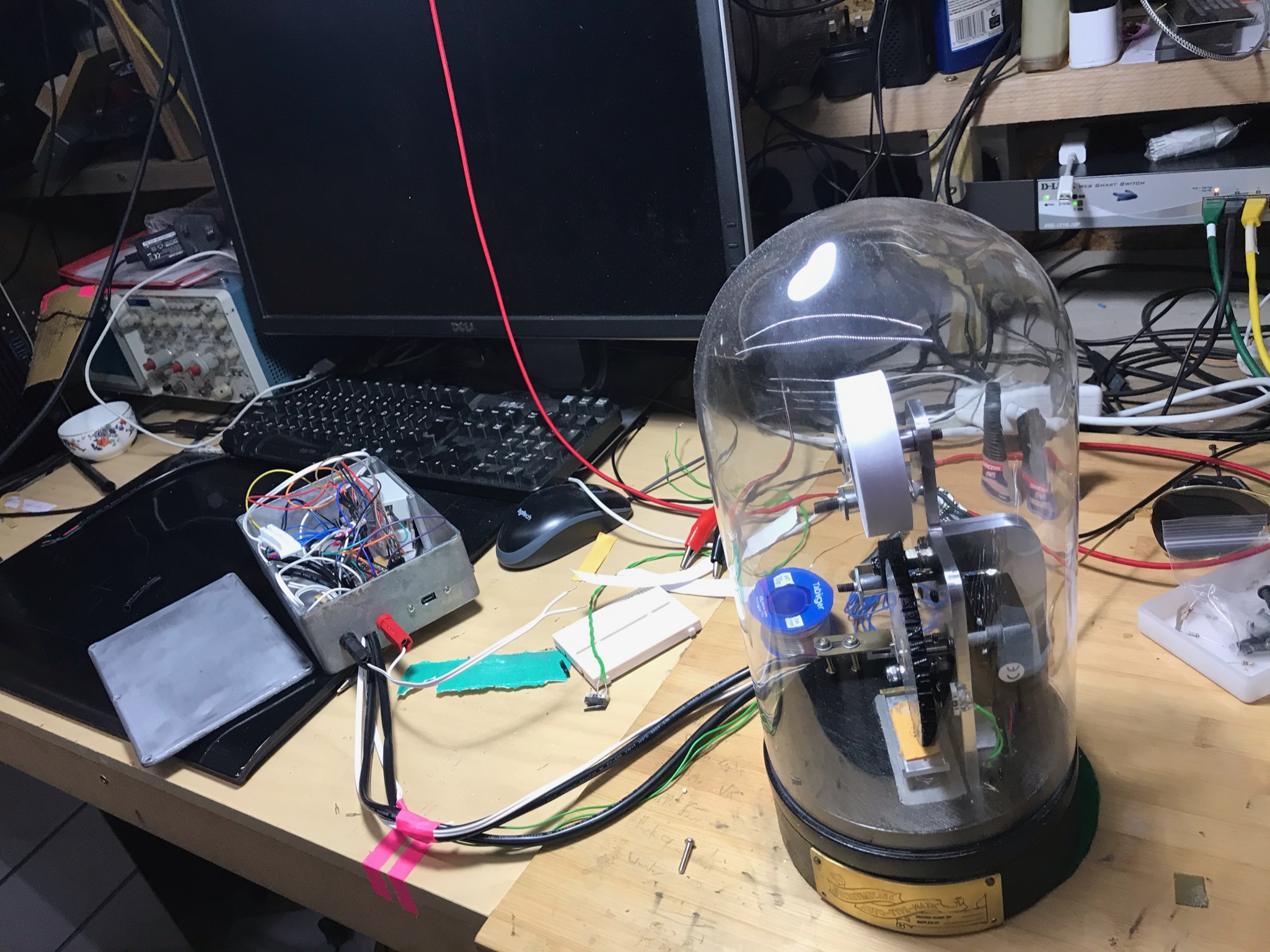
- an Ikea HÄRLIGA Glass dome with base,
- an embossing wheel,
- A stepper to feed paper
- A stepper to move the type wheel
- Some solenoids to push the paper into the type wheel
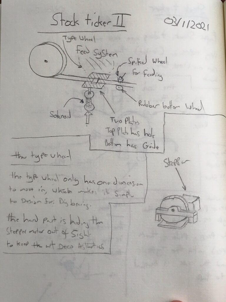
Rough design plan:
BUILD MONTAGE TIME
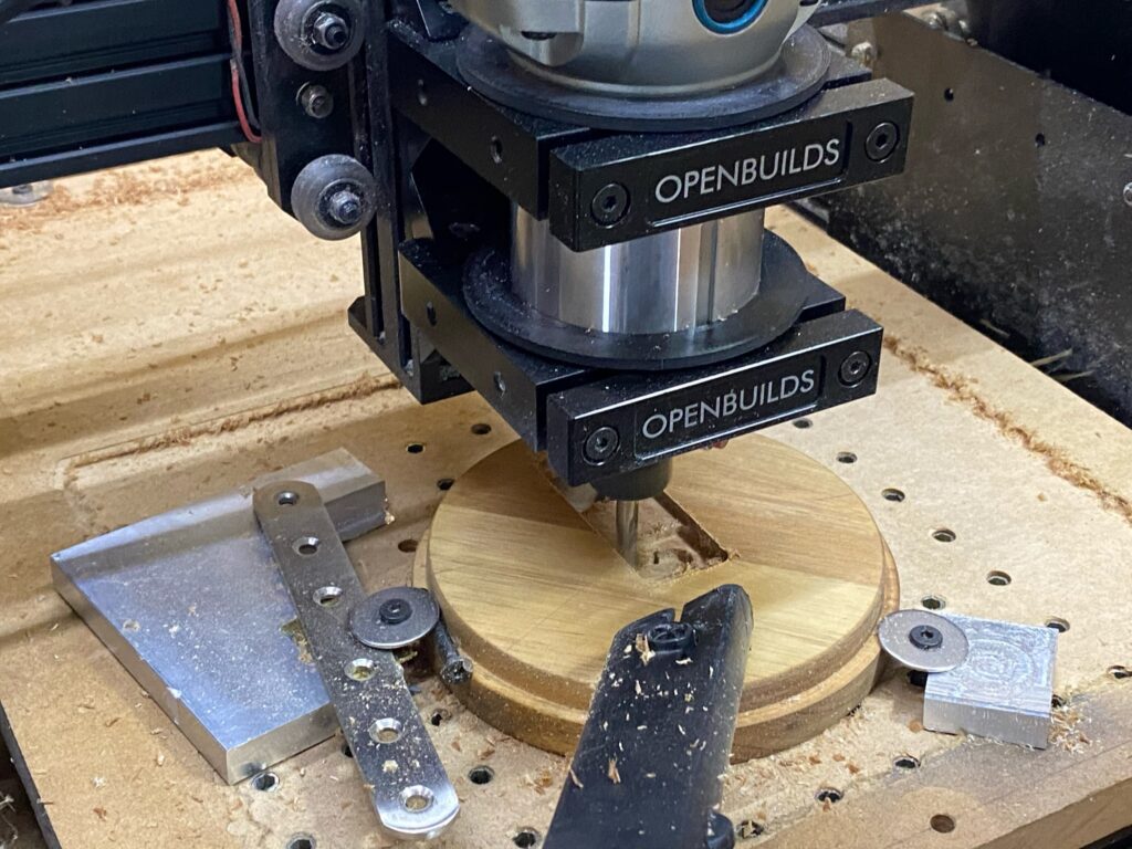
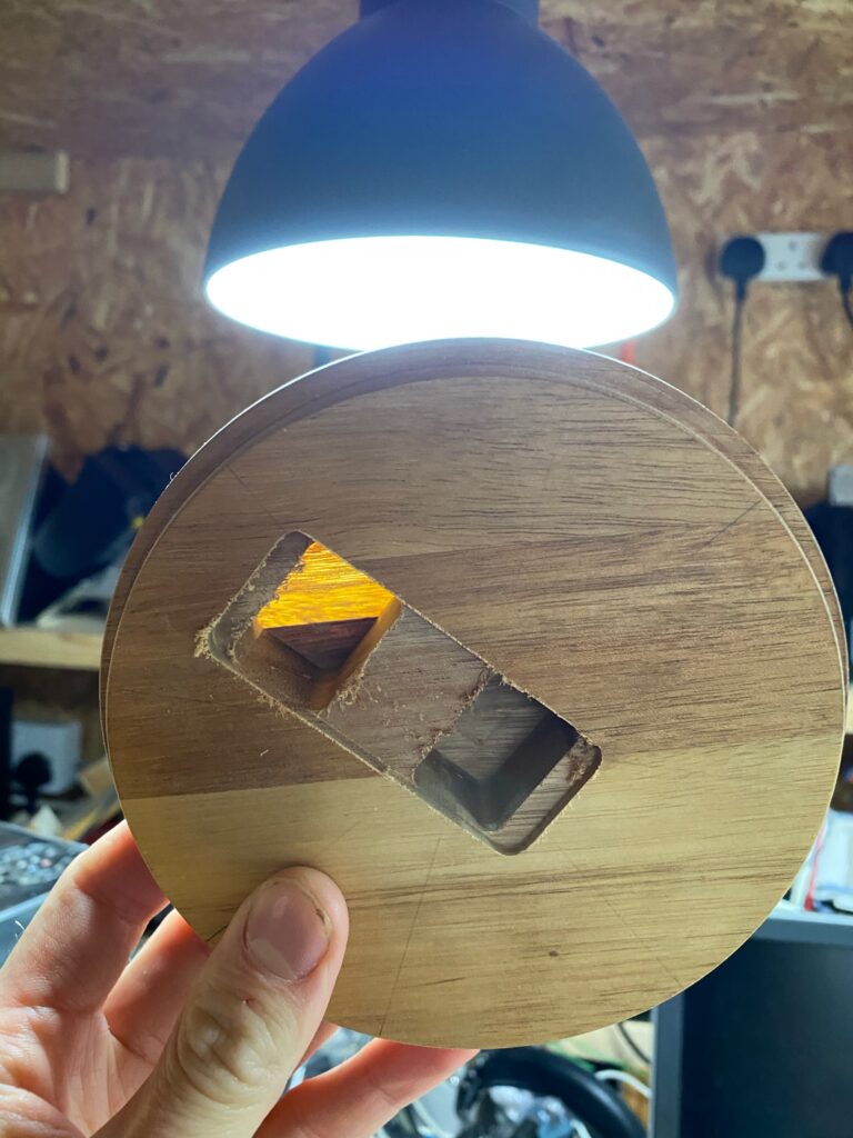
First we need to mill a pocket in the base of the bell jar. This will accept the plate that holds the solenoids that pushes the paper into the type wheel
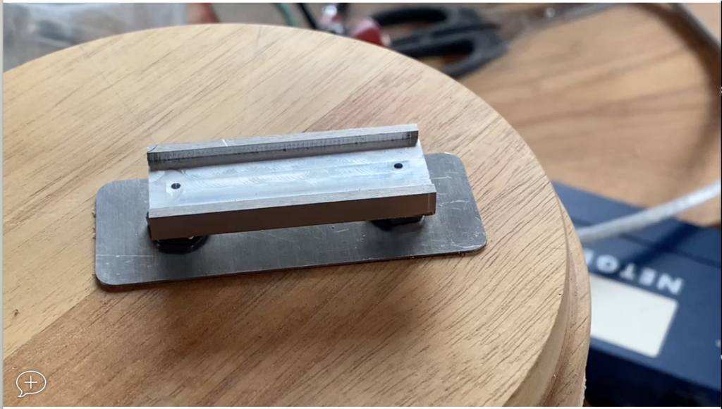
Now that we have the presser plate more or less sorted we now to figure out the way to hold the paper, type wheel, and the various motors needed to manage them.
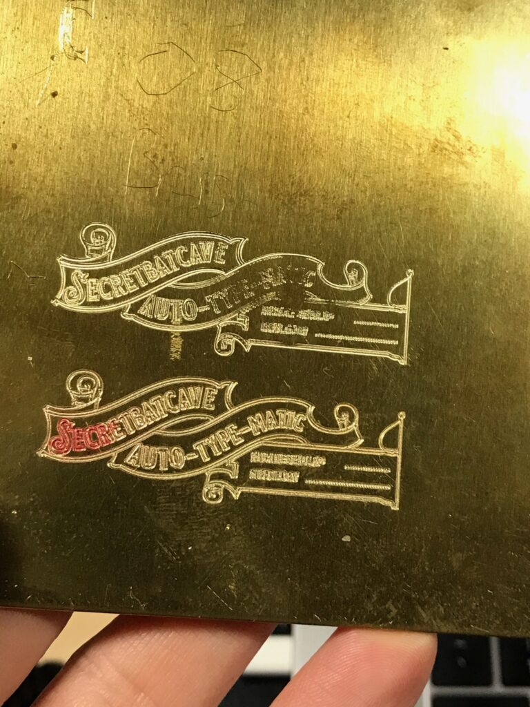
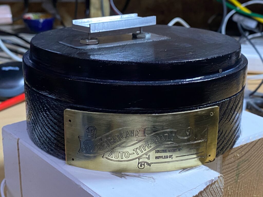
But, before we do structural things, we need a logo. As we are dealing with something from the late victorian/edwardian era, we need a decent logo:
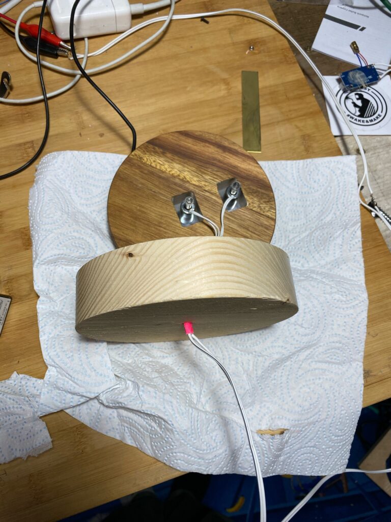
When I was designing the logo, I realised that the stock base that comes with the HÄRLIGA isn’t tall enough to house the solenoids. So I need to mill a base extension:
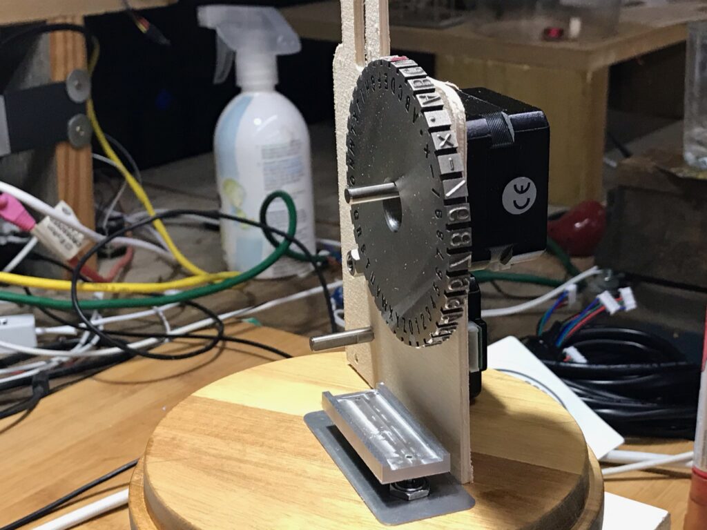
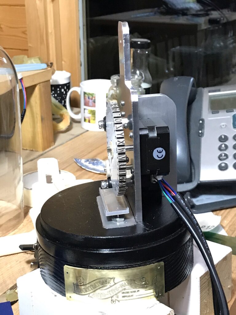
Now that we have a logo, base and paper pressing module, its time to make a “main plate” that supports the paper, type wheel and feed mechanism.
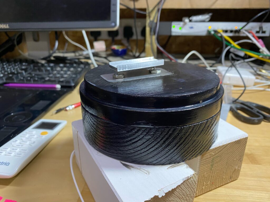
A plain pine base is very un-victorian, so we need to make sure we make it look like its from the 1900s. So we need to dye the base jet black and make it glossy.
I had looked up how to ebonise wood, as I had assumed that’s how they made that glossy black wood. However these techniques don’t work on pine.
So I split the difference and stained the wood with Indian Ink. However the ink will come off in your hands if you’re not careful. So I sealed it all with acrylic gloss.
Now that we have the base almost fixed, we can move on to the main plate. It needs a support to stop it falling over. The typewheel also needs an adaptor.
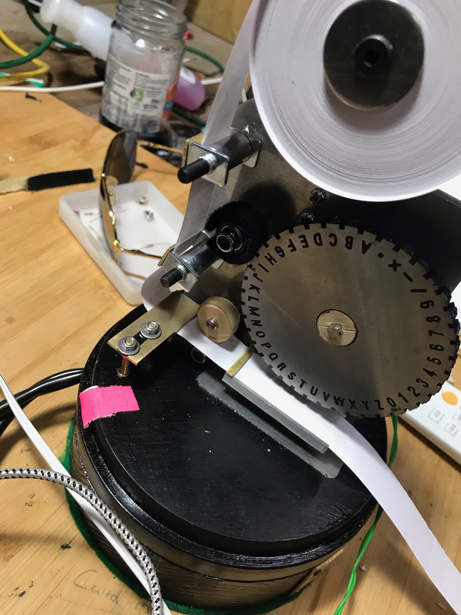
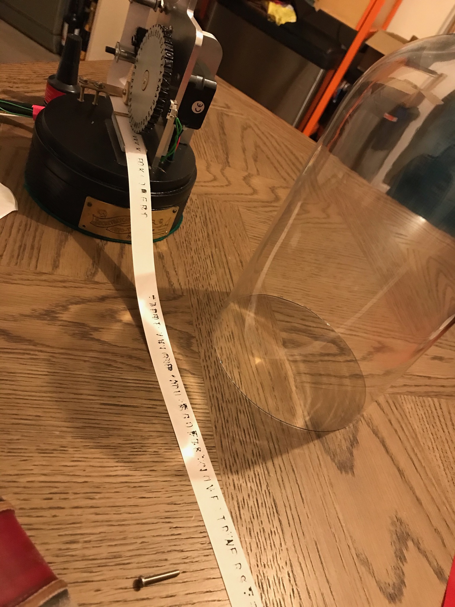
Now, most of the physical build is complete, I need to make sure that I can ink the stamping wheel, and reliably guide the paper into the correct place. After that, its all software and electronics, which I hope is a lot easier.
Part Two: the last 5% takes 99% of the effort
In this phase, most of the effort was spent trying to make the paper feed work without eating the tape. Because the paper feed was not entirely parallel with the presser plate, the paper would jam and crinkle.
There are other problems with this line feed mechanism:
1 ) The feed wheel isn’t particularly circular.
2 ) The wheel is thinner than it should be
It turns out that there is a reason why printers have rubber feed wheels. Paper isn’t a uniform thickness, its also not compressible, which means that the line feed stalls. Add to that, the wheel isn’t circular, means that you need the rubber to overcome the imperfections.
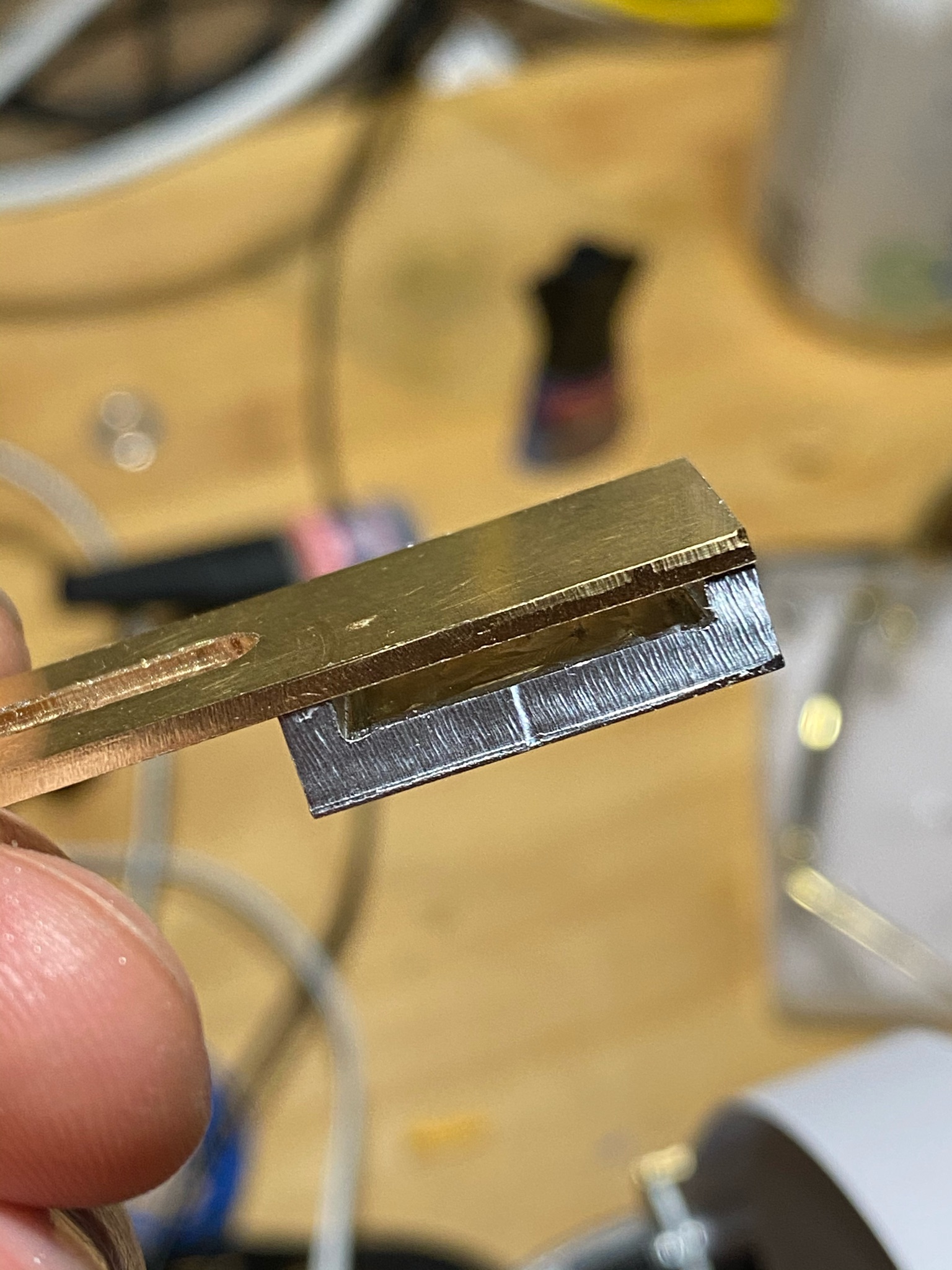
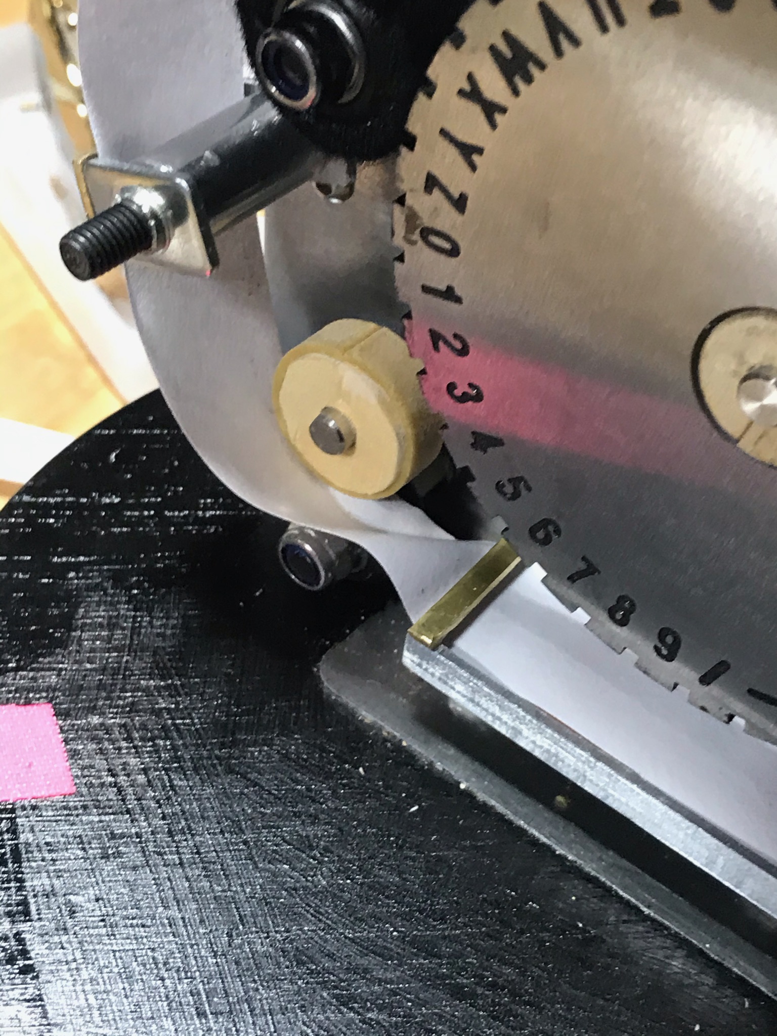
The solution to crinkled paper feeding is to add more guides. This last guide is within 0.5mm of the paper width, this means that there is little wriggle room.
This feed conforming guide is designed to be adjustable in three dimensions. As you can see in the picture below, that freedom is quite important when you fail to install the threaded inserts properly
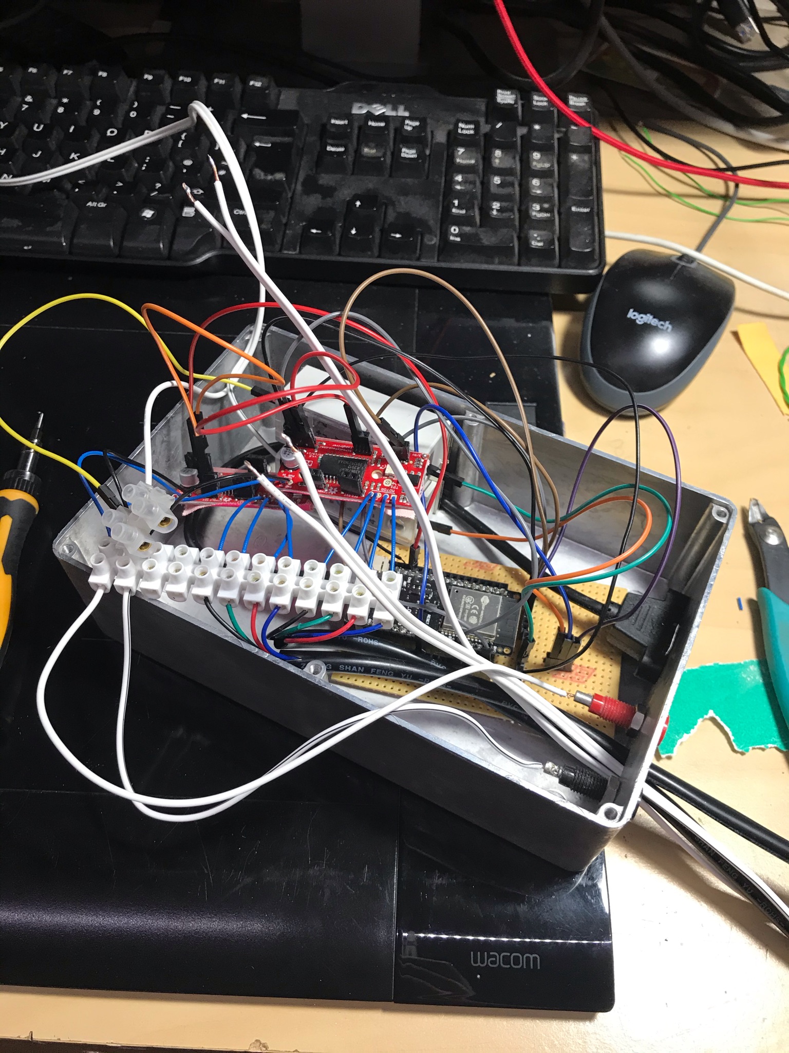
Now that we have something close to a working printer, we need to start thinking about how we make it more durable. All those exposed cables and wires are a hazard. Its even more of a problem when we are mixing +-24volts and 3.3/5v.
Firmware
Obviously we need some firmware to get things moving. I’m not going to bore you with this for too long, its just micropython counting steps. Each letter is 10 steps from each other. So its just a case of homing the wheel, applying a magic offset to make really sure we know where “zero” is.
Software
Because I’m going for a retro look, I decided that I should really create a proper TUI. In this case I have used rich, a fancy young library for python that makes very sexy widgets easy to use
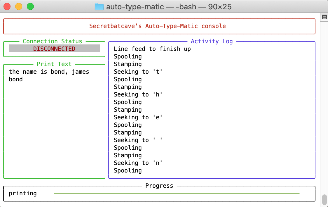
When I figure out how to record a terminal session, I’ll show you what it looks like running. Until then, you’ll have to take my enthusiasm for how smooth it looks on account.
Conclusions
Can you make your own stock ticker? yes, is it easy? not overly. But its not the hardest thing I’ve ever made. Was it cheaper than the £4000+ original? you betcha. The most expensive thing was the type wheel, costing a cool £35.
Does it sound cool? yes, yes it does.
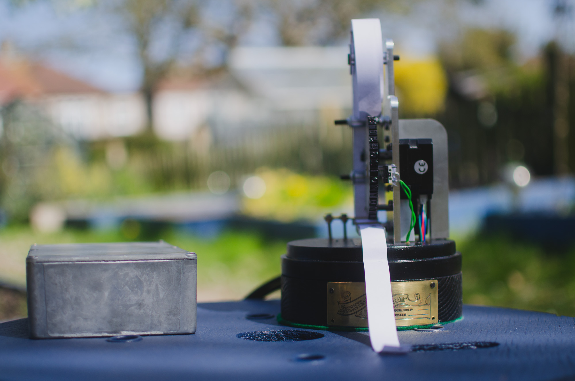
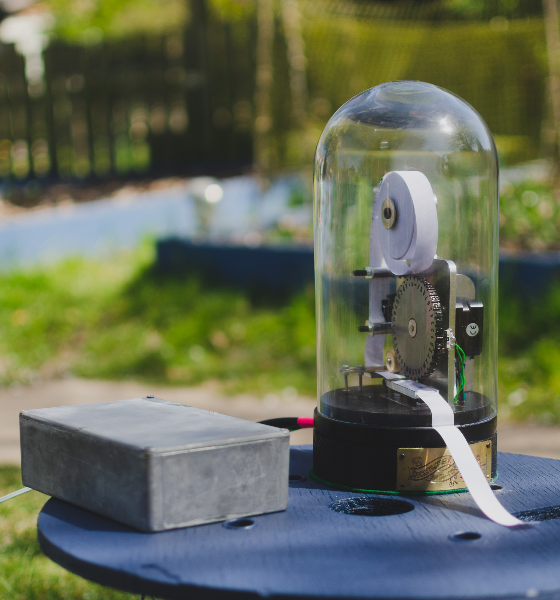
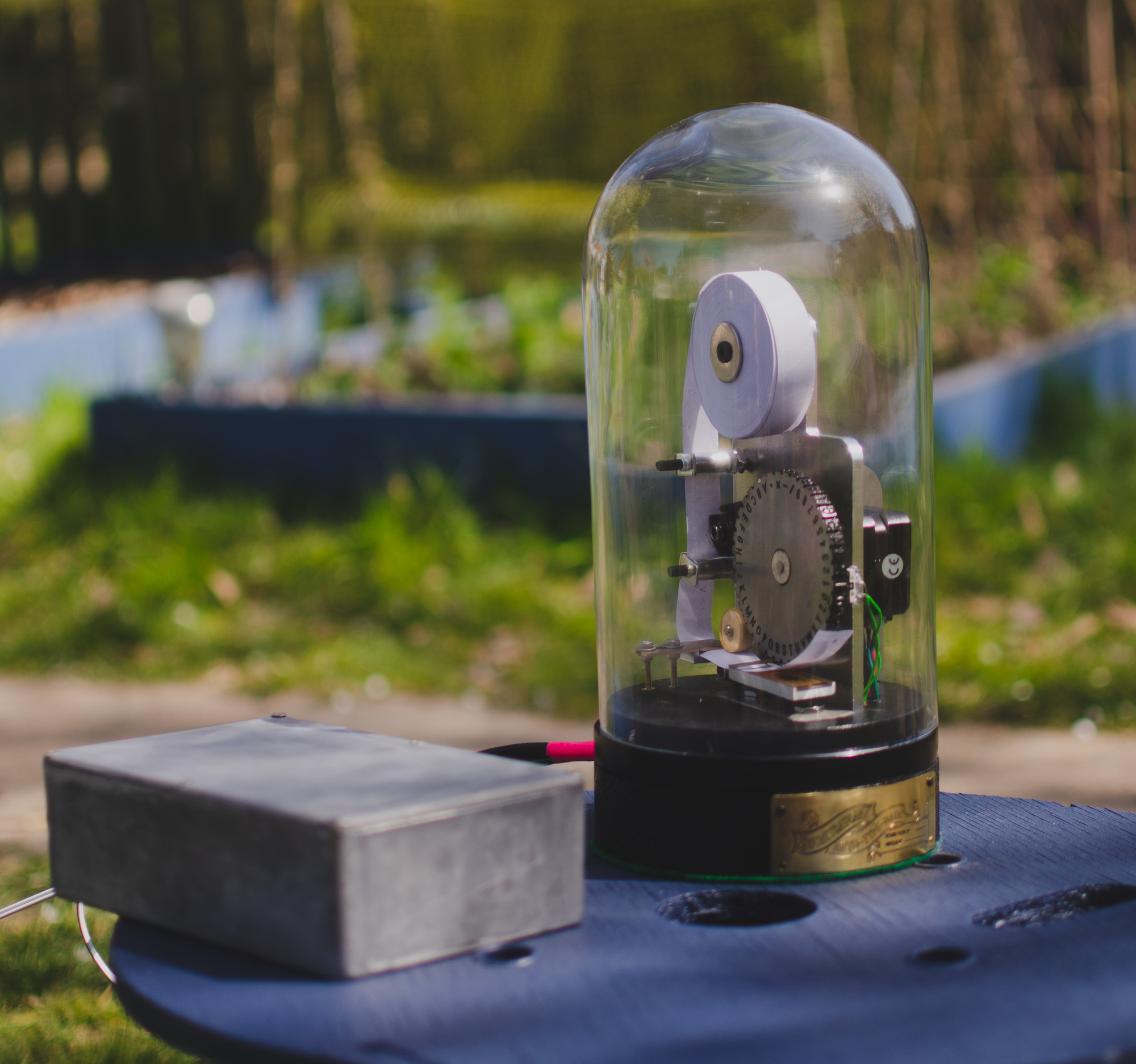
Final sexy pictures