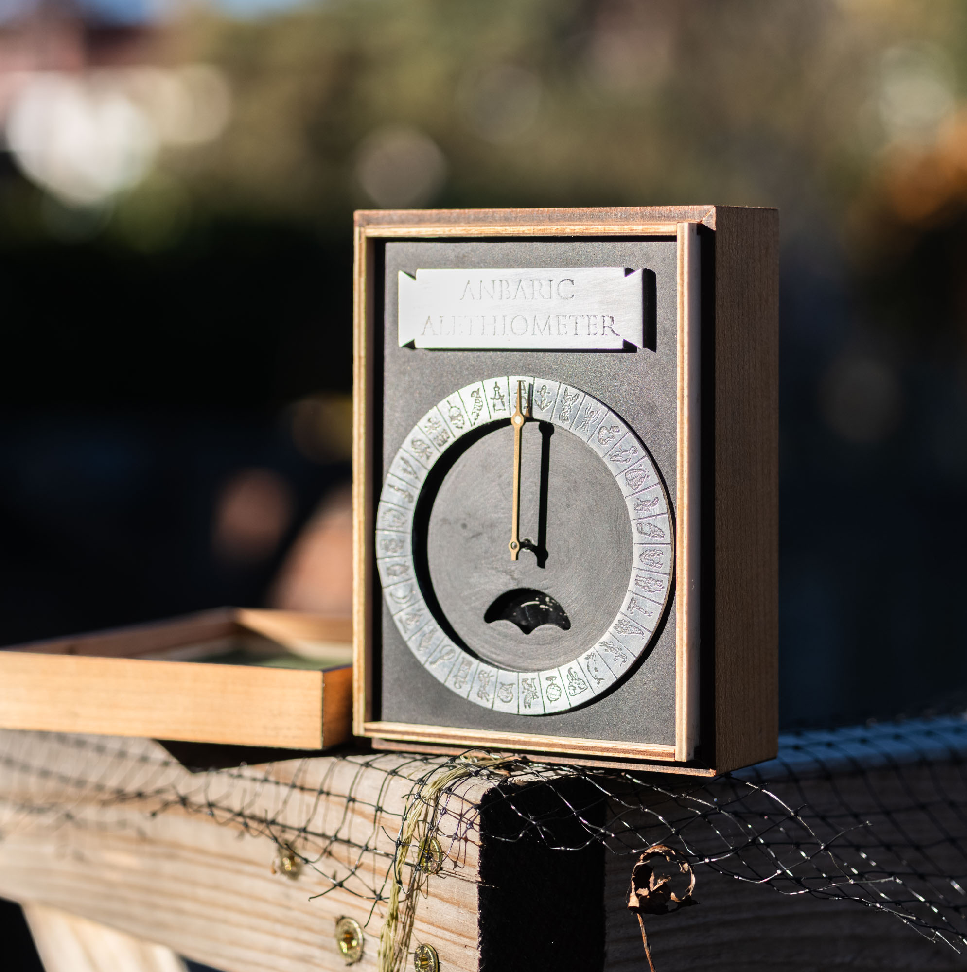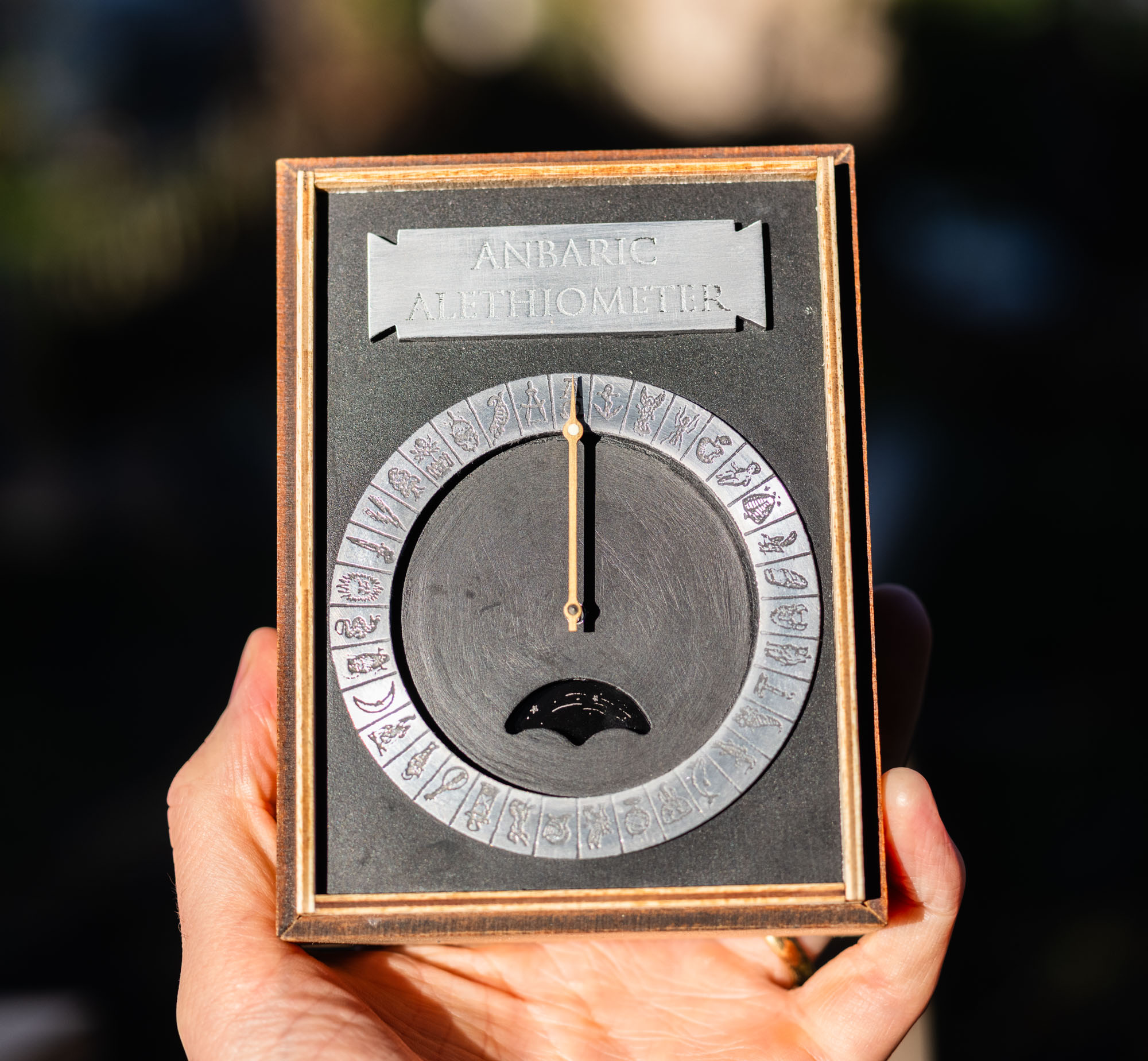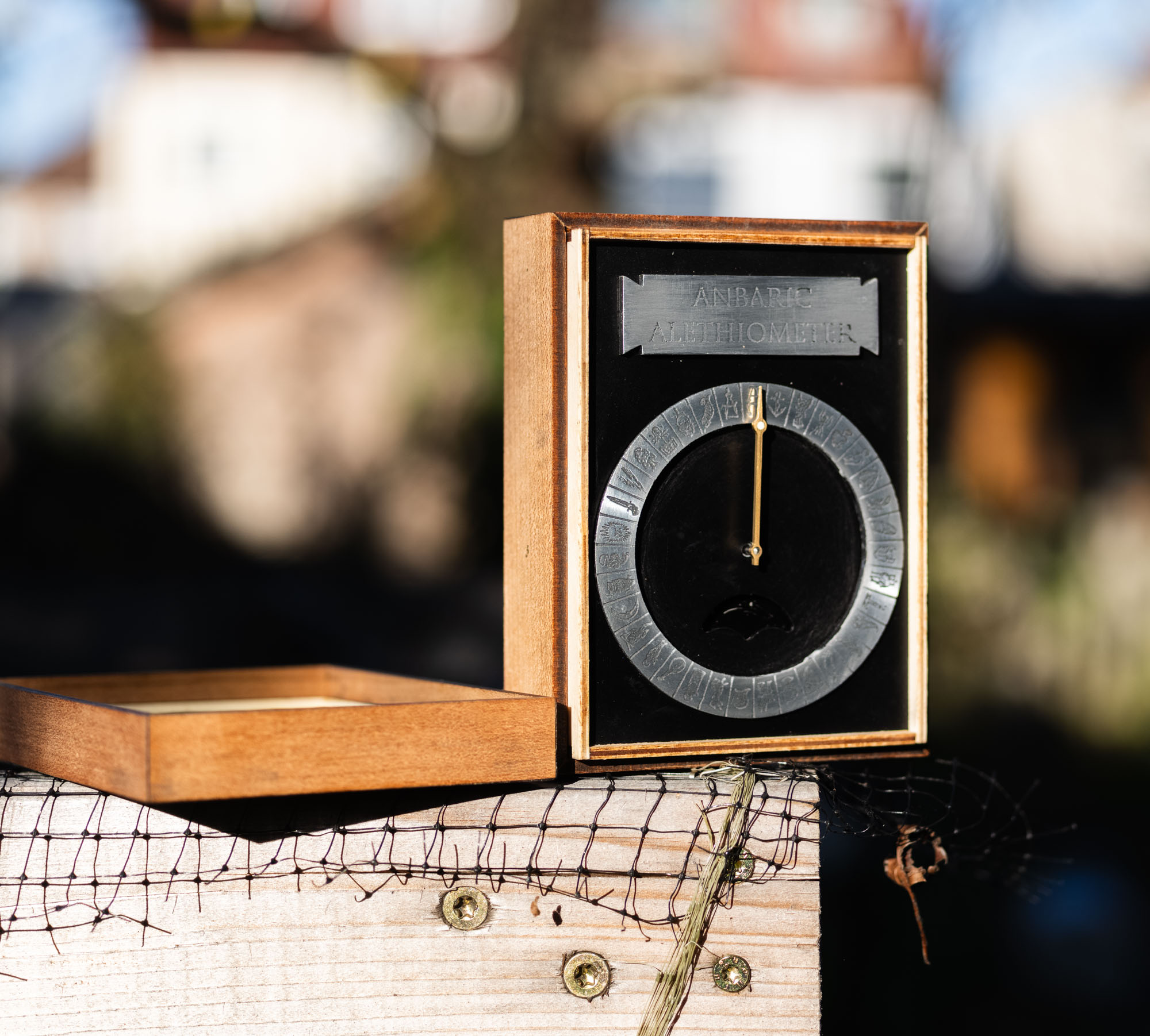
Greetings, as you might know, Phillip Pullman has released the last book in the trilogy that makes up “the book of dust“. This series follows Lyra from a baby to a stumbling insecure teenager. Frustratingly the teenage Lyra is full of self doubt, and is almost “roger-esque” in the way she carries herself. Anyway, this re-ignigted my thoughts about the Alethiometer.
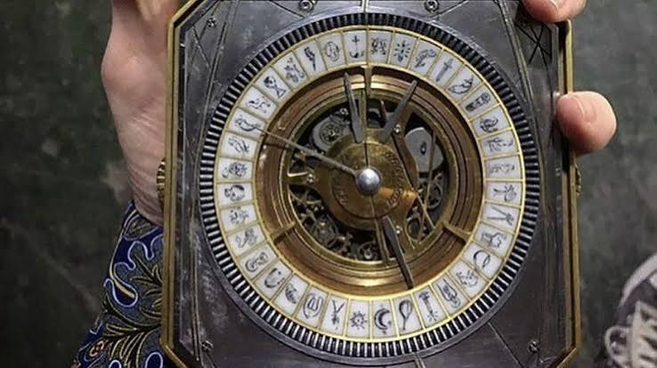
For those of you who’ve not read the book or seen the BBC or Movie adaptation, the Alethiometer is a clock like deus-ex machina that guides Lyra through the many worlds of the book. She sets a “question” by moving three needles to the symbol that matches her question most closely. Once set, the long needle moves around the dial, indicating the answer.
We learn later on that the needle isn’t actually attached to the mechanism directly, and the three driven hands are for show. This means that any “modern” remake wouldn’t actually need the three “question hands”
This is convenient for me, because I want to re-make the Alethiometer in the style of the TV/movies; 1920 retro futurism. This means Aluminium, brass, sturdy wood and businessman like finishing.
I did briefly look to see if you can buy one already. They are either cheaply made tat, expensively made tat, or an unobtanium prop
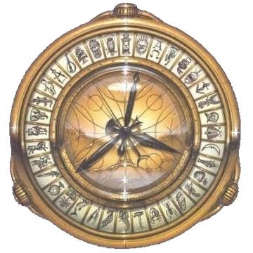
Design Time
As mentioned, I want my design to be inspired by, but not a copy of, the original. My thought is that if a university was going to research into the Alethiometer, they would try and recreate one, then assuming that was possible, make a few research versions to take out and test in various conditions.
My Alethiometer is not going to be gold and ornate. Its going to be a precise, but semi-mass produced “scientific instrument” from (our) 1920s. This means classical nods in the design, The use of Aluminium to make it exotic for the time. (see Eltham palace using aluminium leaf for the ceiling)
This means a walnut square case, and precise, but not ornate decals. This is reflected in the design inspiration:
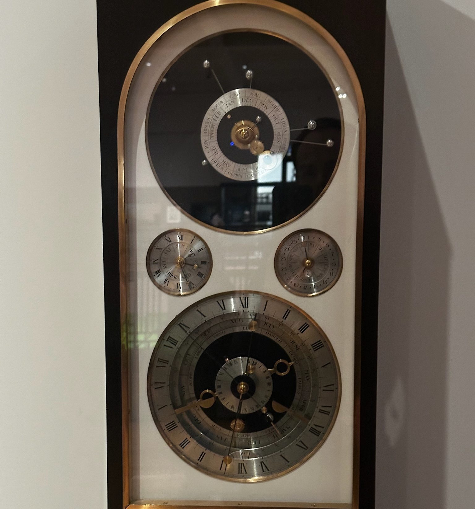
More inspiration comes from the rather amazing Electric clock museum. The curator there has spent a lot of time making the collection available online. Basically the 1920s are the peak of electro mechanical things. To me, they look wonderful, and I want to capture some of that spirit in my design
Preliminary Design
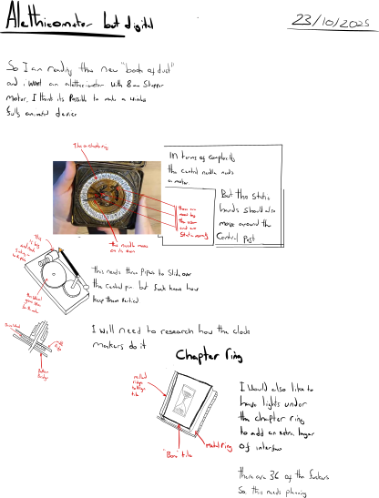
Now, none of you are going to be able to read my writing. So let me transliterate for you. The thing I am working out here is how to take an 8mm stepper and convert the motion into a sweeping hand. I also go through the motions of making the “chapter ring”. This is the circle of symbols that go around the edge of the “clock face”. The thing I worry about is having to source/make all the illustrations, then transferring them onto something permanent. I did look up fake ivory. This is basically cow horn, which is laser etchable.
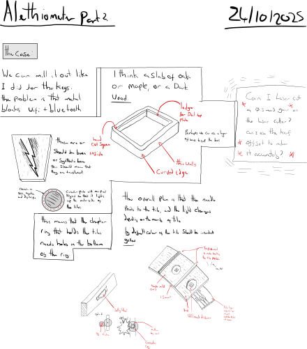
Here I am thinking about the case. I was originally going to get a solid piece of bog oak, or just plain oak and hollow out a pocket to put the instrument in. However I discounted that as its expensive and error prone. It would also mean that you’d see a lot of end grain, which isn’t pretty or in keeping with the style.
I also tried to work out if I could illuminate each symbol, and how I can either move the needle manually, or provide an input to trigger the needle to move. Both turn out to be impractical. Neopixels are too large to fit under the symbols.
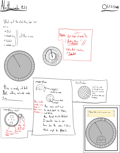
This is where the design starts to crystallise. I will have a small subdial with a moon phase to indicate certainty, and a large “Breguet” with a chapter dial that contains the symbols. I do not have the time to experiment with Guilloche sadly.
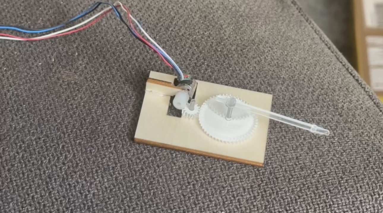
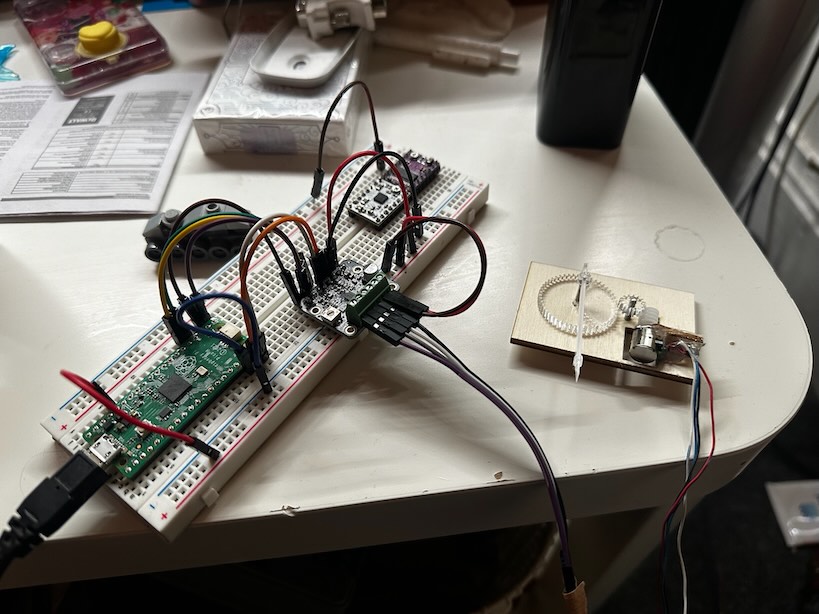
I set about making a dodgy prototype, which to my surprise worked first time. Normally mechanics are a painful game of iteration. I then spend a good while trying to figure out how to package everything nicely. The electronics were a little more trial and error. Trying to get a stepper driver that could work at 3.3v or even 5 volts was challenging. However Adafruit came up trumps:
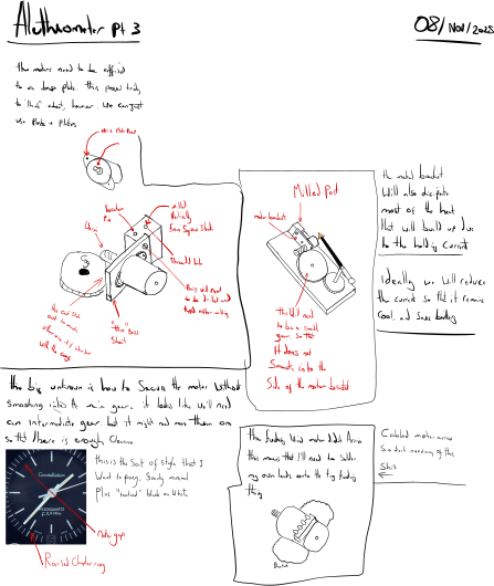
Finally I figure out how to package everything into a small-ish package. Because I want a “moon phase” sub dial (to give a “confidence” to the symbol) I need to pack two mechanisms in a small place.
I gradually hone in on a multi-bridge style system, this means milling out a pocket in the top bridge to hold the moonphase subdial, and the bottom plate holding the motors, worm gears and pinions.
The milling was reasonably easy, although not without fuckups. Here you can see that the workpiece holding gave way, and that we missed a step in when changing z height. (Line in the centre of the edge)
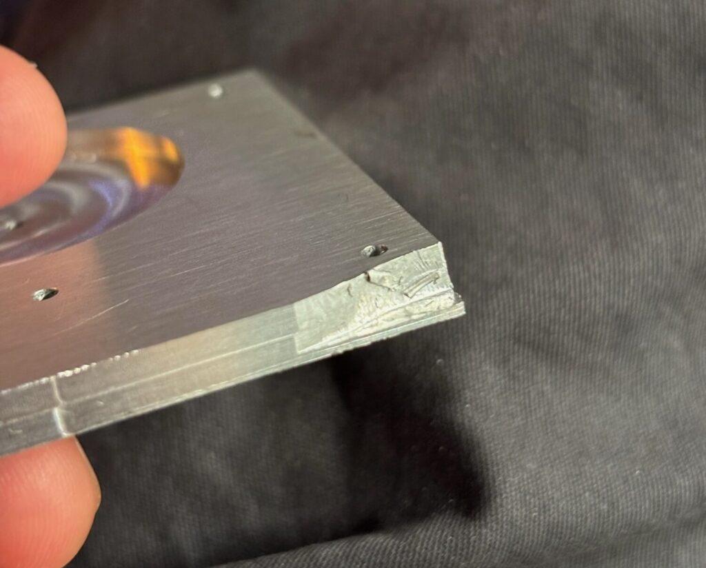
We can polish the seam out, but the gouge will have to stay….
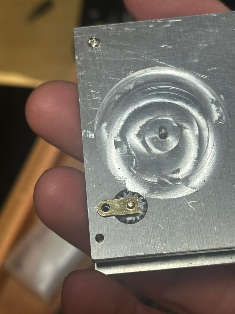
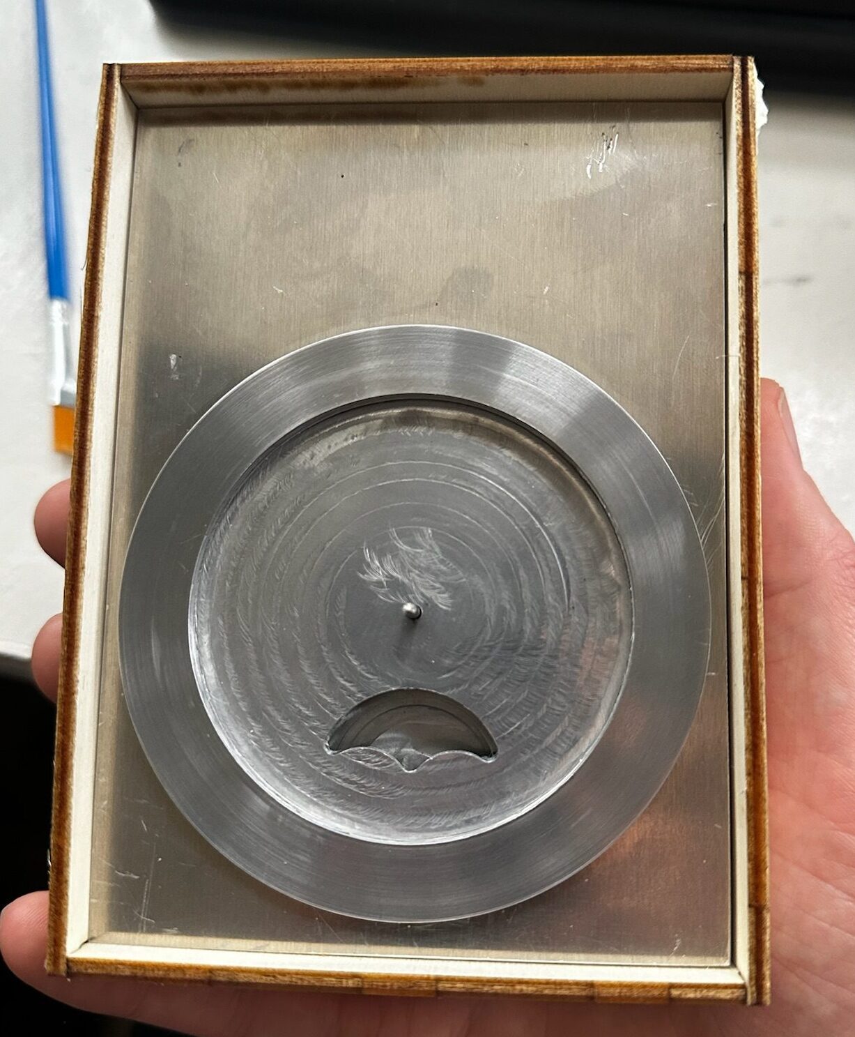
This pocket holds the moonphase dial. The dial has teeth around the edge, which means that the little pinion can rotate the whole dial
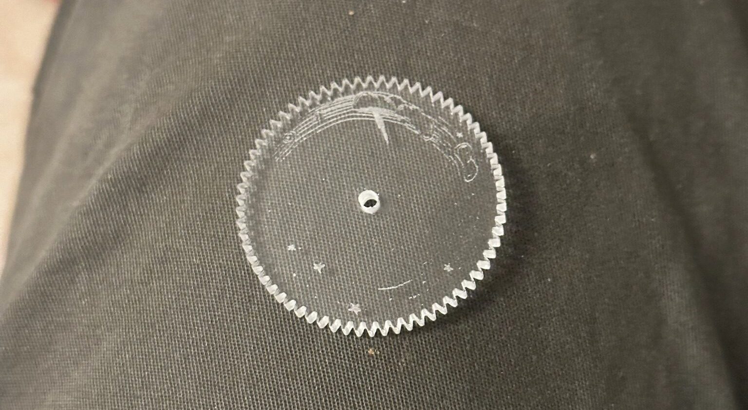
This is the test piece. This proved that the laser could resolve the tiny details needed to make this work. The final piece was sprayed with black matte paint.
Chapter ring
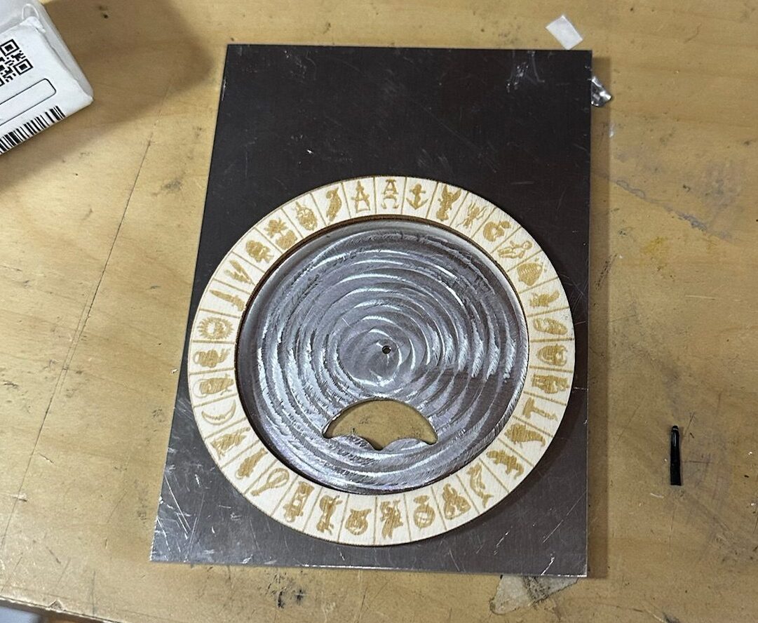
The dial is simple, a circle pocket, with a chapter ring. This is the thing that turns a dodgy clock into an Alethiometer. However I need somehow transfer symbols from the computer onto the chapter ring, which is metal. There was lots of Alethiometer art out there, but none of it was quite right. In the end I had to redraw each figure based on the original poster (see the second image from the top of this page). I did this in illustrator, which meant that everything was a vector. This was great for scaling.
Having managed to get the artwork sorted, the first stage of testing was burning it into plywood, this proved that the dimensions were correct. Once that was proved I needed to try and etch aluminium to see if the detail is preserved:
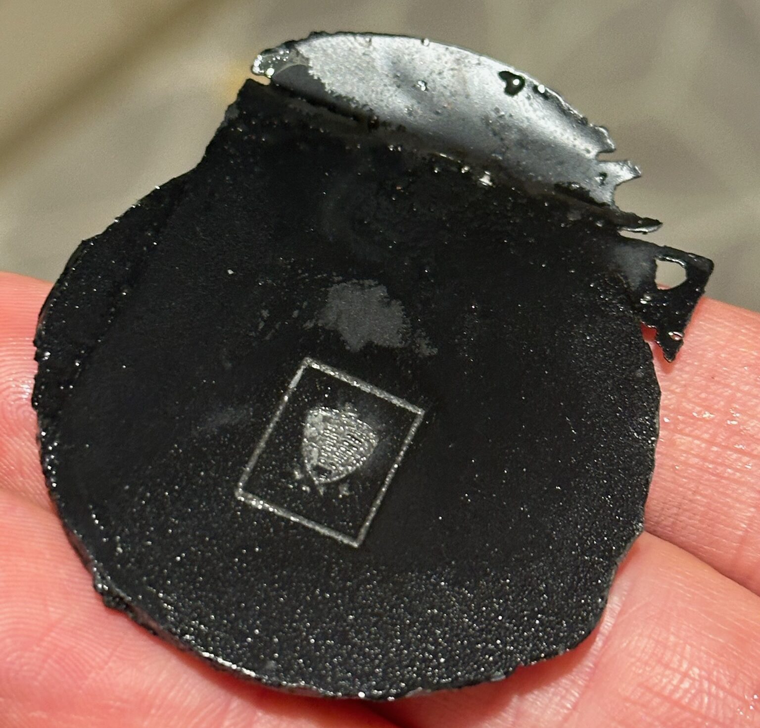
In this test the aluminium is sprayed with paint, and the pattern is lasered off to leave the metal exposed. I can then use electrolysis to electronically etch the bare metal away. The paint forms an electric proof mask that stops the non-exposed parts from being eaten away by electrolysis.
There are a couple of things that I learnt:
1) if the water gets too hot, the paint flakes off and you lose detail
2) its best to have the etching piece vertical in the water, as the bubbles cause the crap to be lifted away, meaning that you don’t need a agitator.
3) Aluminium only takes about one minute thirty seconds to etch about 0.3mm
4) of you etch too deep, it looks rubbish:
5) all non-covered bits of metal will be eaten away.
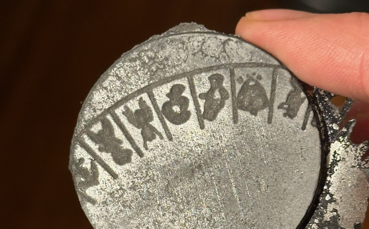
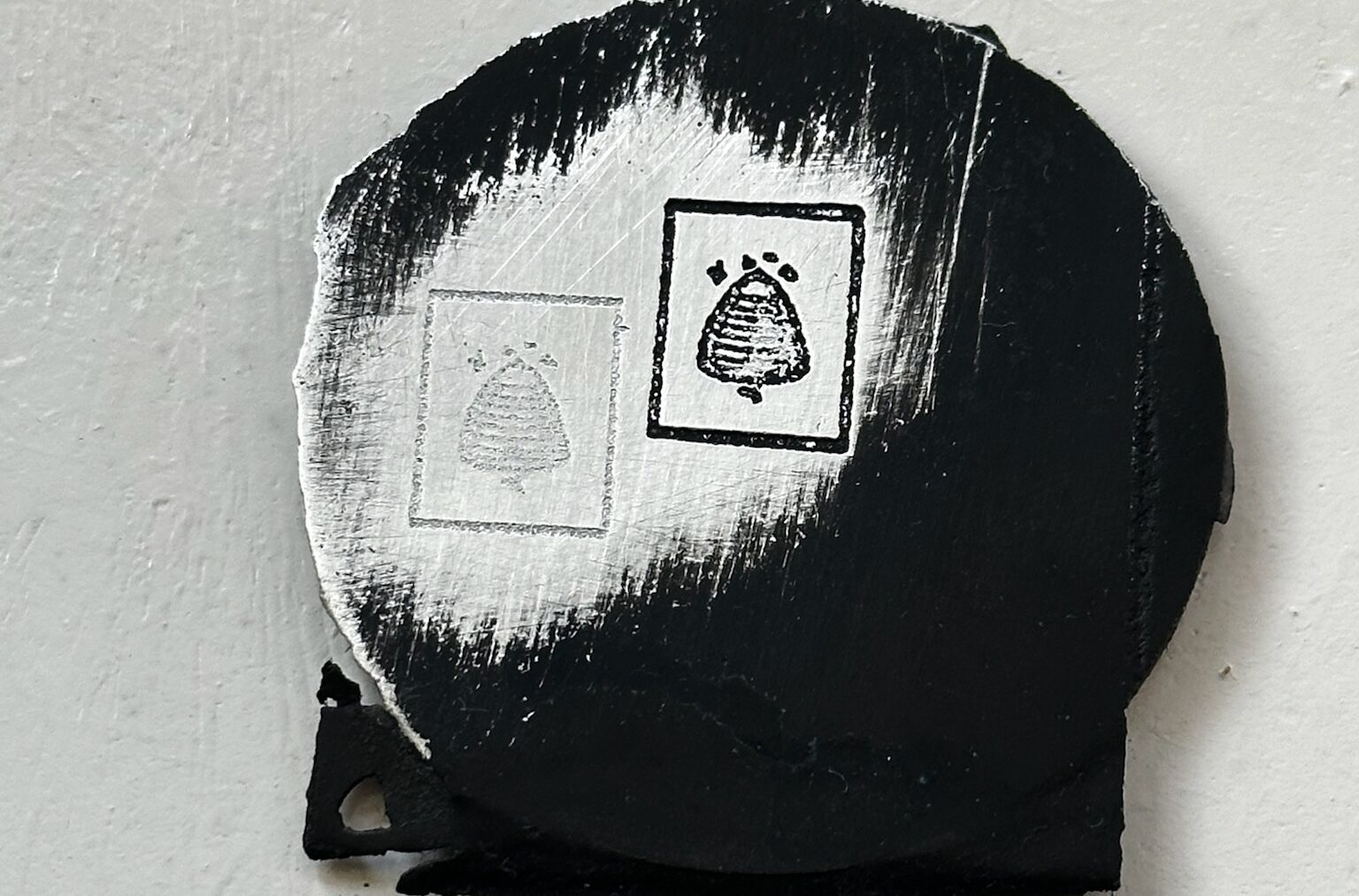
Here you can see that I’ve finally managed to balance the detail/depth ratio so that its visible, but not pitted like it is above.
I took all that experimentation and applied it to the chapter ring blank:
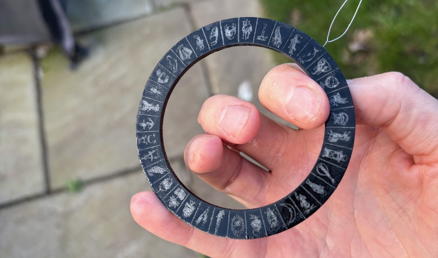
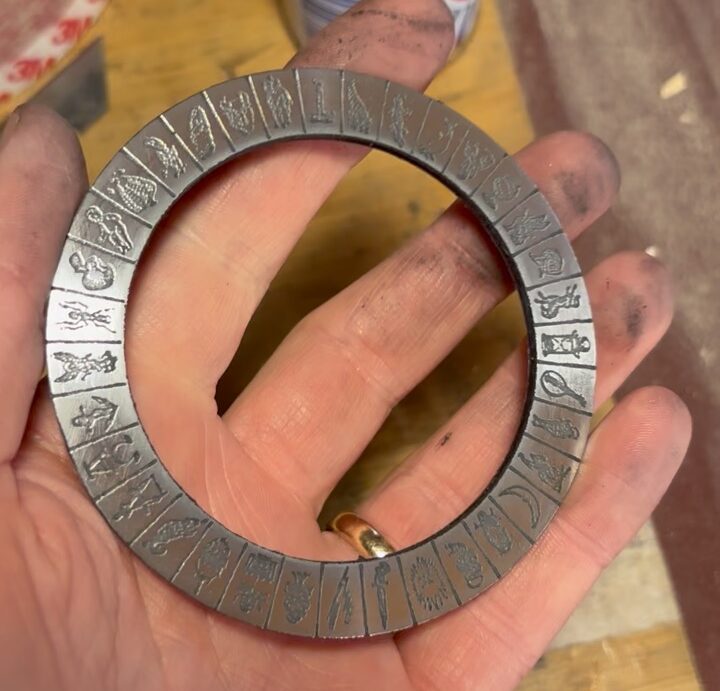
Did I get it right the first time? did I fuck. I took it out too early and the sacrificial electrode was nowhere near big enough to cover the entire workpiece. Fortunately it wasn’t very deep, which meant that I could slap it on the lathe, sand it down and start again without having to remake the blank.
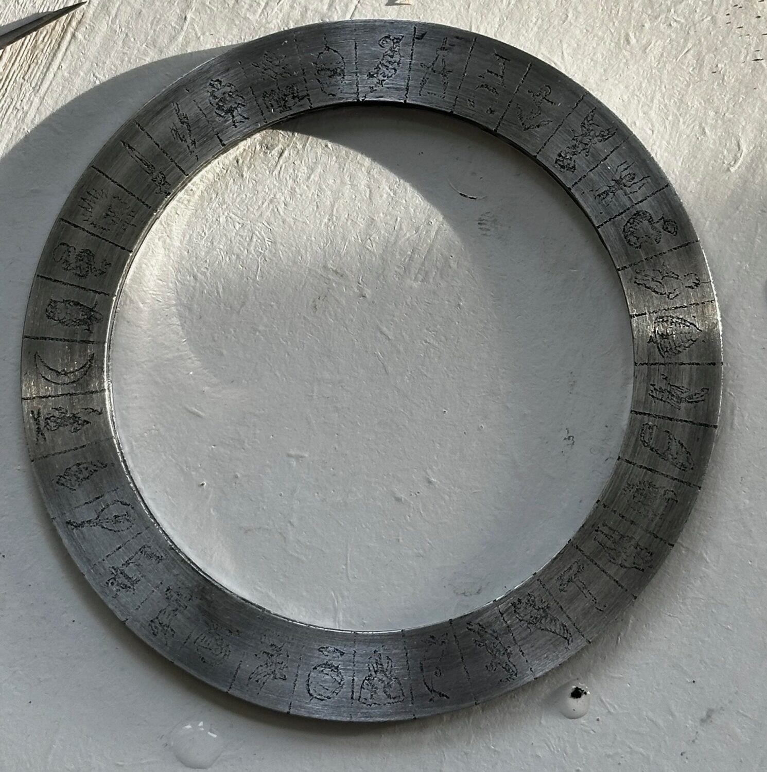
A quick re-etch later:
Big Dial time
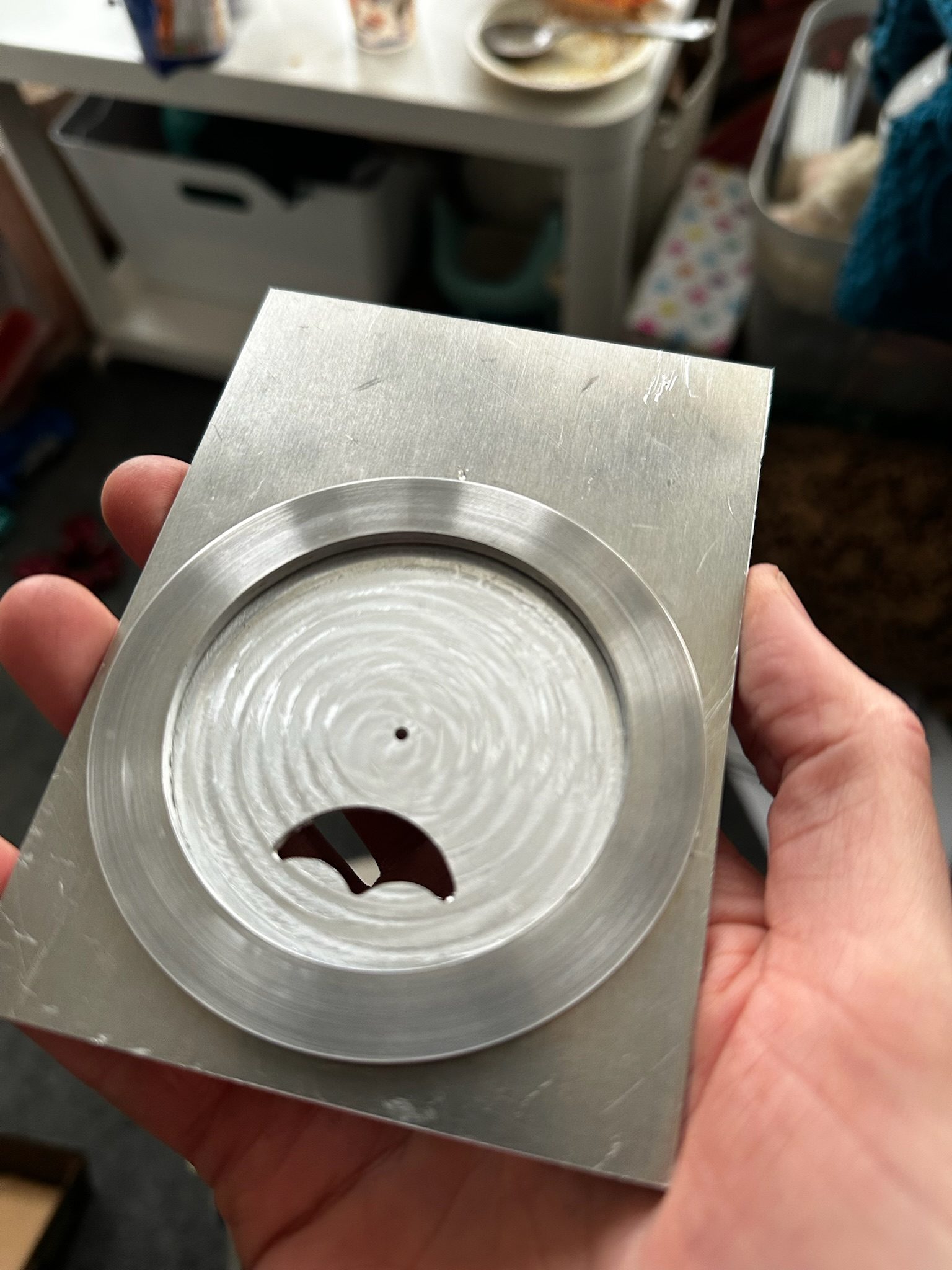
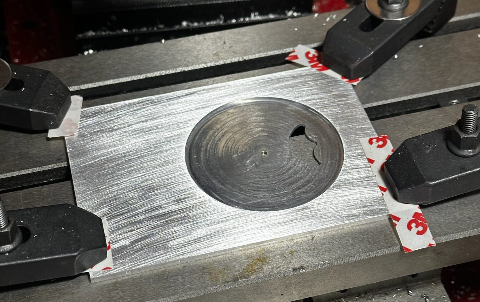
The thing that’ll make or break this project is the dial. if it looks shite, then the whole things off. Fortunately its quite easy to machine. Its a few circles and a large rectangle. Here you can see the unetched chapter ring, which looks surprisingly good.
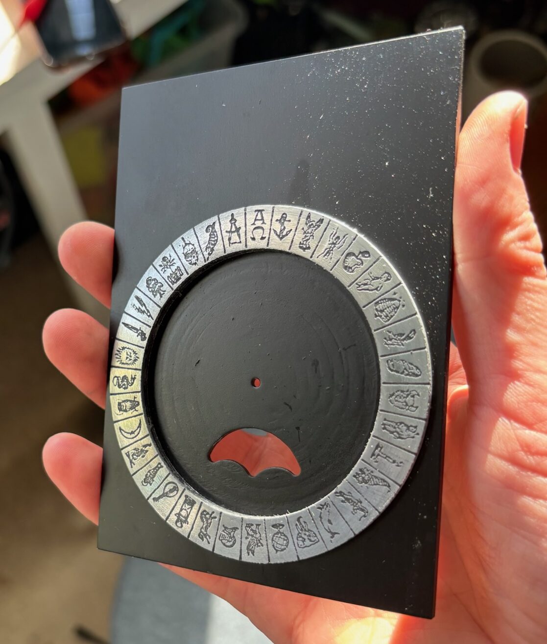
Looks fucking great. However you can see the machining marks under the paint job. These marks are more pronounced because the dial was vibrating under the endmill. The clamping I did caused the sheet of aluminium to bend up slightly. I should have glued it to a larger block of something solid.
Making a movement
The motors I am using are tiny. This means they fit in tiny places, but are bastards to mount. Here you can see the little brass collar that I created to hold the motor. Remarkably I managed to make them accurately enough to be a press fit.
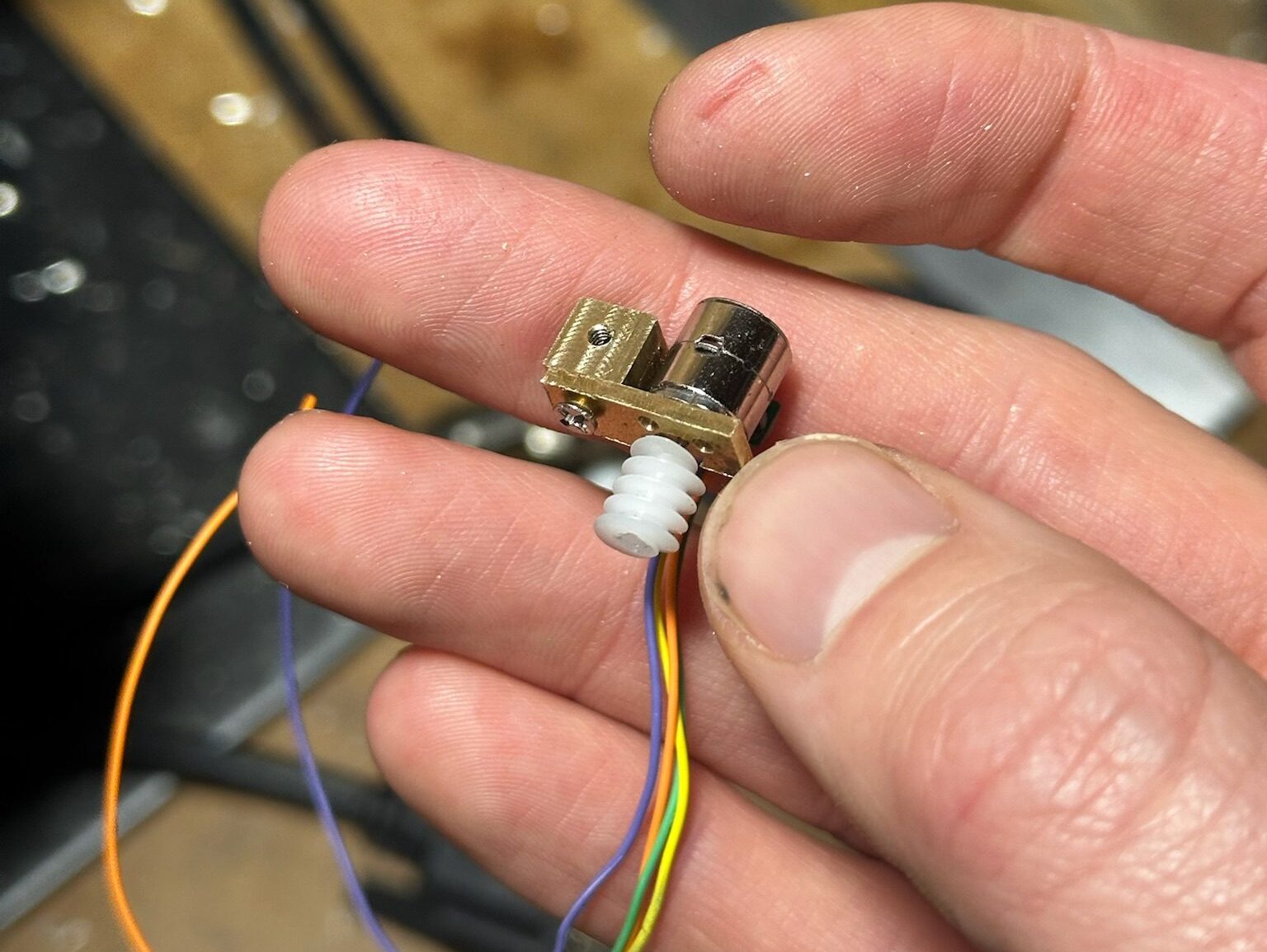
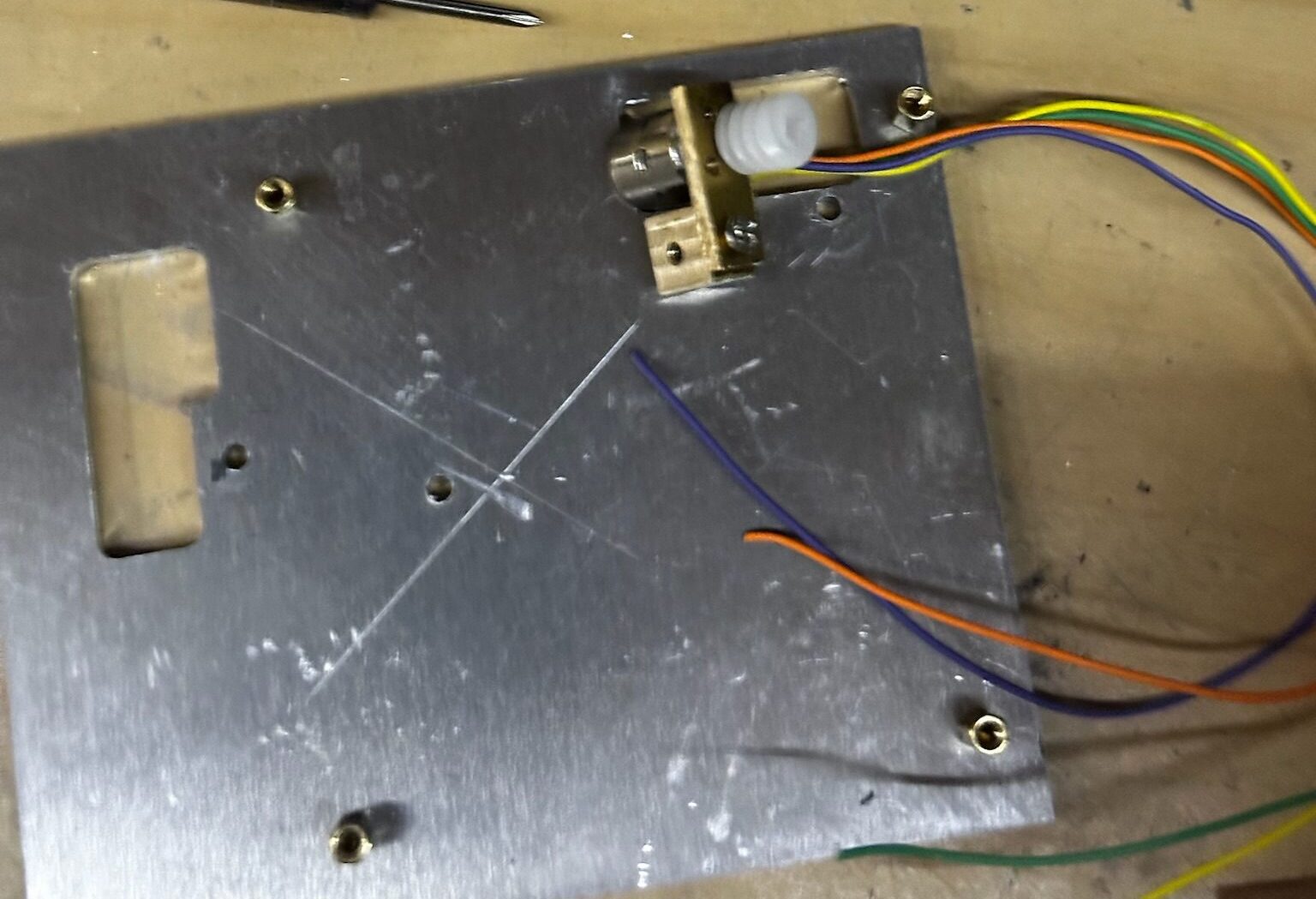
Here is the bastard little motor on the bottom plate.
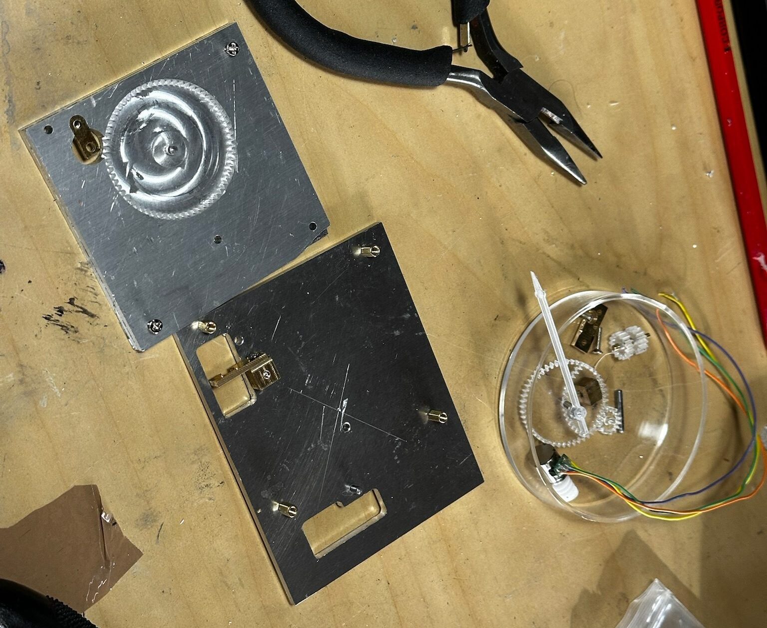
The two bridge plates ready for assembly. I’m using brass stand-offs to join them together. they are cheap, precise and easy to fit. They also don’t look all that nasty.
Now, movement and case go hand in hand, this is the first iteration of the inner box. The idea is that this case holds the movement and the dial, and we can then add an outer box around it to make it look nice.
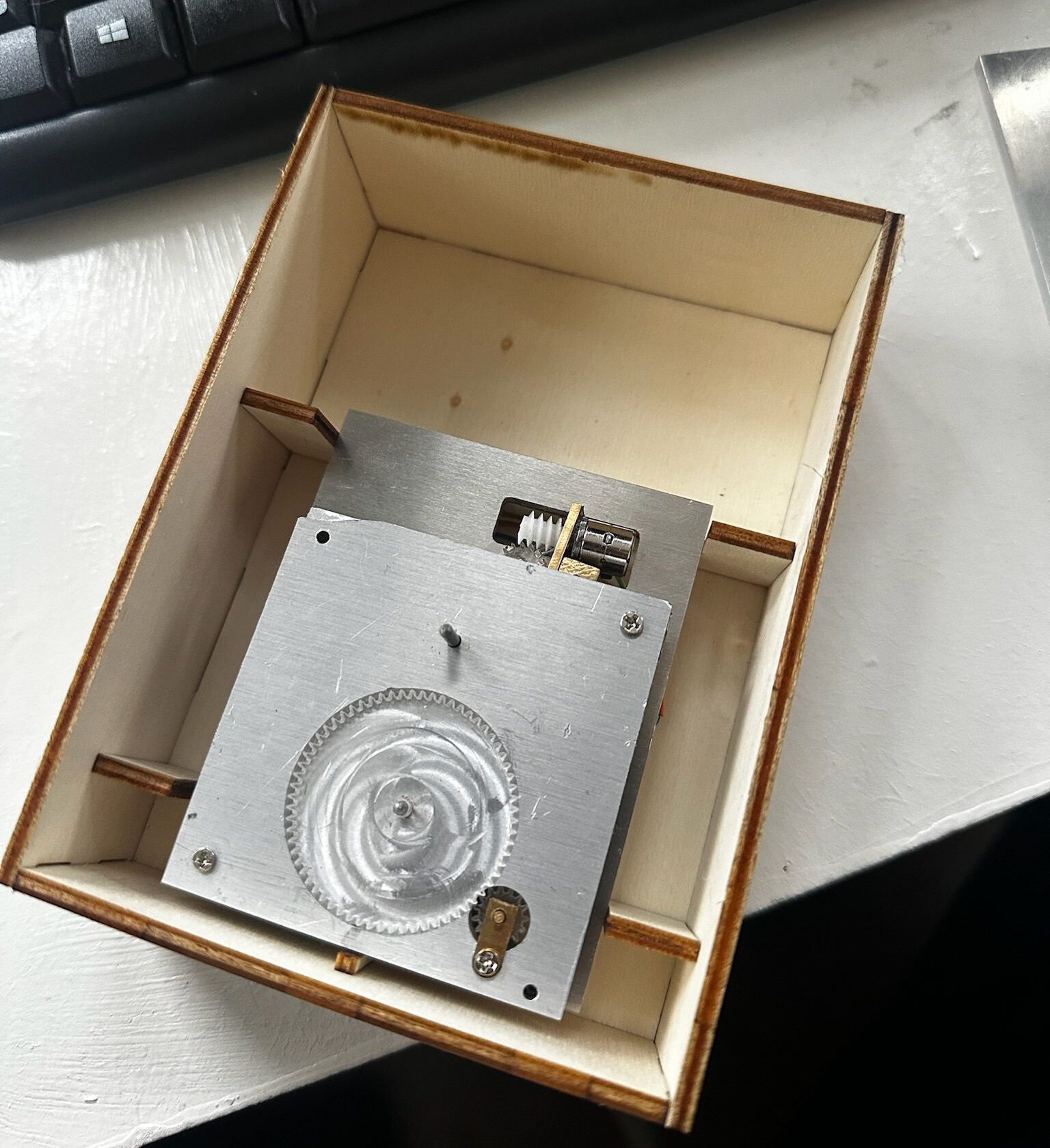
This is a simple box but with custom wooden harness to hold the movement in place. Without it, the movement slops around and the posts won’t line up with the holes for the dial.
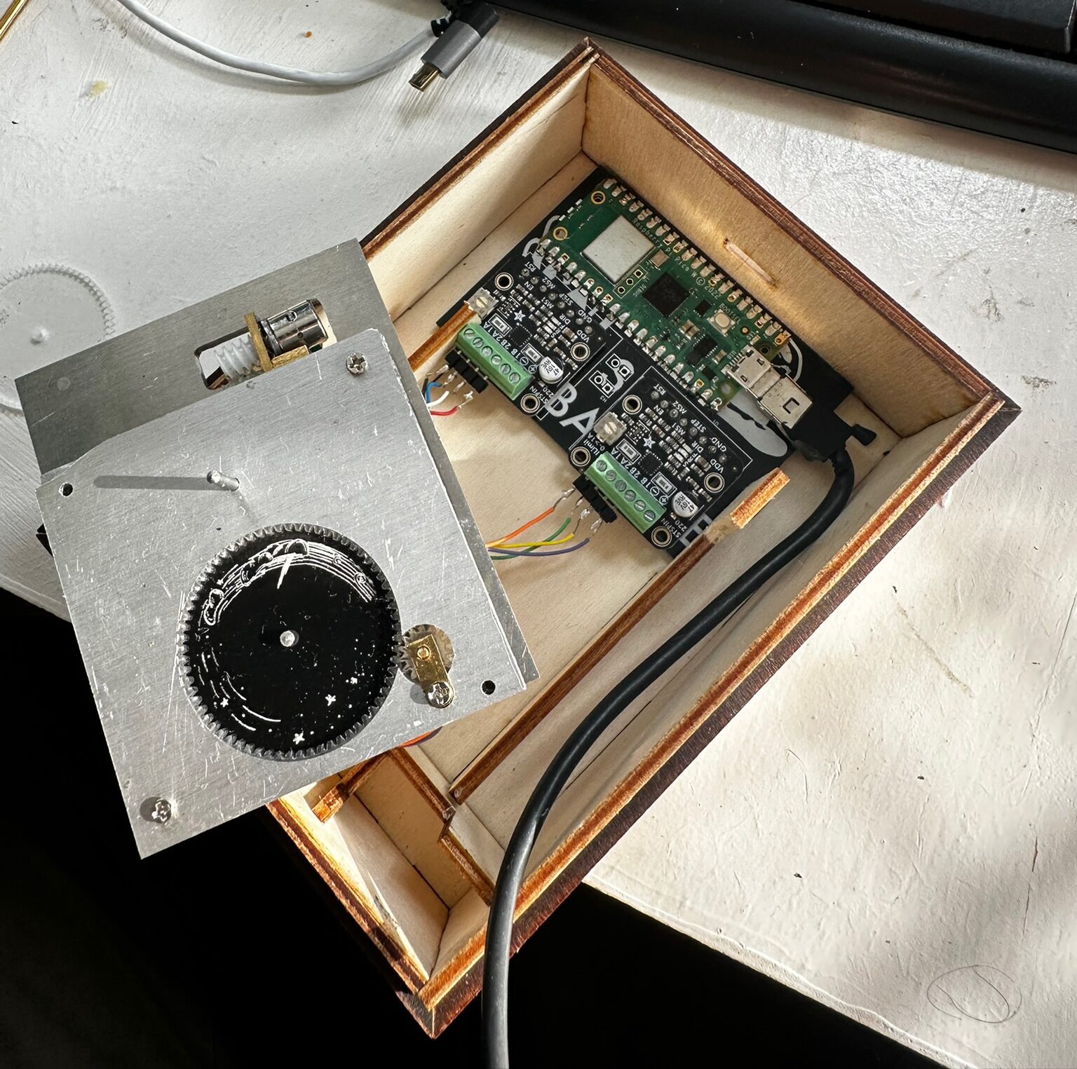
Sorting out the electronics requires a custom PCB. a castilated RP2040-w is soldered directly to the board along with the two stepper motor drivers. The tiny little stepper wires are soldered to some headers, and then the headers are screwed into the terminals.
Its not as compact as it could be, but its easy and maintainable. Should the motor fail ( they are cheap after all ) they can be swapped out quickly and easily.
Had I been brave, I could have used a PCBA service and embedded everything directly onto a smaller PCB. However this would have added another two dimensions of testing and fixing.
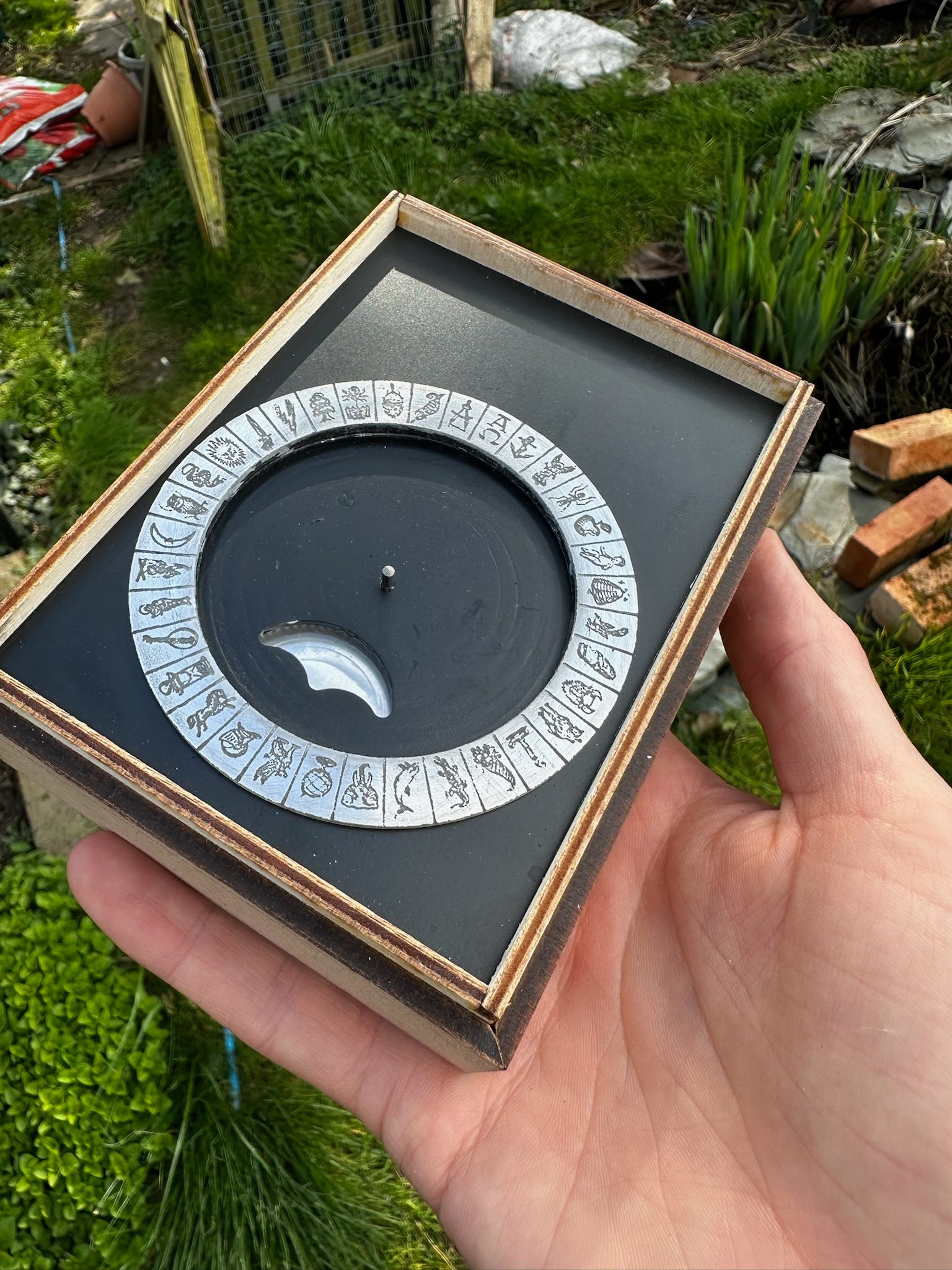
Looking nicer still, with the outer case glued to the inner case, and the dial painted. The outer case is made from cherry veneered laser safe MDF. Sadly my laser cutter isn’t capable of chamfers, so I did that manually, to variable success. I tried to make a high quality seamless box that looked like it was made by skilled craftsmen. The verb try is the operative word here. It still needs some sort of oil to make it “pop”.
Hands
I need a big arsed hand to point to whichever symbol the machine is “thinking” of. As this is one of the more obvious parts of the build, it requires some design thinking.
Clock hands are a bit like typefaces, they each have a “smell” of the era that they were designed in. Most people don’t care or spot it, but if I was one of those people, I wouldn’t be making this, would I? As with everything watchmaking, there is a lot of fluff about different designs, however there are only really a few types.
We are going to use “Breguet” hands. They look like thin stalks with an arrow on top, but the arrow is a circle with a point on top. There are literally thousands of books worth of noise about the design of these hands, I am using them because they look nice, are easy to make, and have a convenient hole to put luminescent paint into.
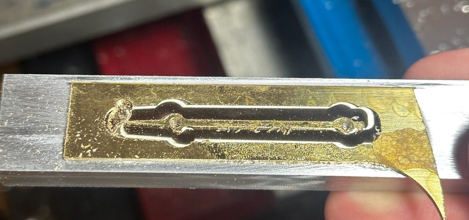
I’m making them out of brass, because thats what I have lying around in 1mm sheet, and its a bit more ductile than aluminium at that thickness. Here I taped the brass to a lump of aluminium so that I can keep it clamped in the CNC.
I was using a 3mm endmill and going quite shallow to keep machining forces down. However if you look you can see that the workpiece escaped its clamps and the top/bottom are no longer symmetric.
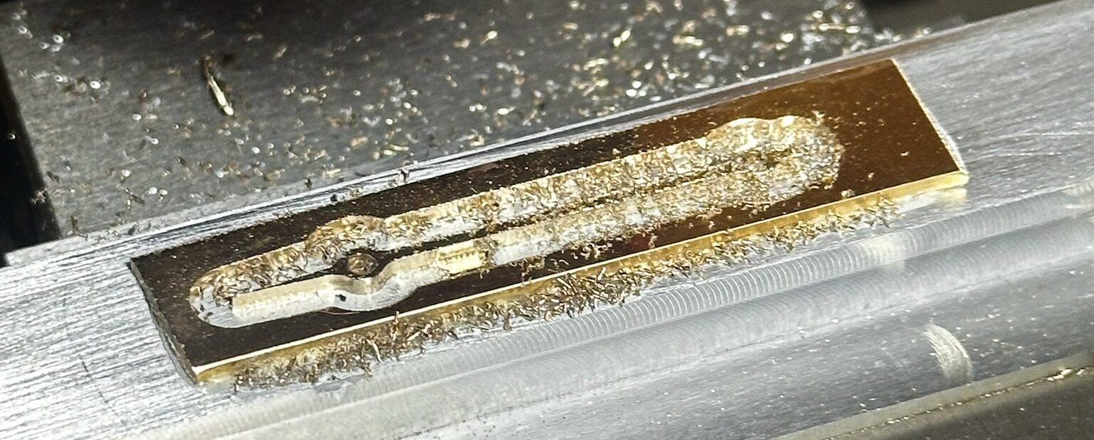
This is much better. Managed to get to full depth without any oopsies. I used a 1mm drill to cut the two holes first. My spindle tops out at 5000 RPM, so anything smaller than a 3mm endmill becomes intolerably slow.
Putting it all together
We have a box, we have a movement, and we have some electronics. Now we need to put them all together and write some firmware. I’m not going to concentrate on the firmware too much. The only special thing I did was to use PIO to make a custom pulse generator with ramping to make a smooth acceleration/deceleration motion.
Now, if you’re a glutton for “slow” content, then I have the video for you. You can see me re-assemble the Alethiometer, complete with my frustrated noises, and the faint sound of fireworks.
Sexy photo times
Alas, not of me in sexy clothes, but me holding the Alethiometer